Novel lighting speeds seal inspection
The production of rubber, elastomeric, and plastic seals and “O” rings is a highly competitive business with numerous companies producing a variety of products. To differentiate themselves, companies often design their own molds using CAD/CAM systems, mix their own compounds, and mold parts in computer-controlled presses.
To further differentiate themselves from their competition, companies are investing in machine-vision systems that inspect top and bottom surfaces, contours, defects in surface curvature, and the dimensions of each seal after it is manufactured. In this way, any defective or out-of-tolerance seals can be automatically rejected before being packed and shipped to the customer.
“One of the main challenges in developing a system,” says Joachim Linkemann, manager of Basler Components (Ahrensburg, Germany; www.baslerweb.com), “is that each seal must be viewed from both top and bottom, and a 360o inspection of the inside and outside must be obtained.” To do this, Basler has developed its vario2, the fifth generation of a seal-inspection system designed to inspect “O” rings measuring between 10 and 50 mm in diameter.
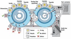
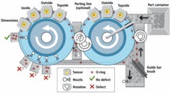
Parts are fed from a feeder to a conveyor belt where they pass a separation unit that presents each seal to a series of two inspection sensors (see Fig. 1). Parts are moved over to a rotating glass plate at up to 4.5 parts/s and pass up to five vision sensors that inspect the height, topside, outside, and (optionally) the parting line of the seals. Then they are moved through a belt turn conveyor that flips the parts over. The parts are then presented to a second series of inspection sensors that perform topside, outside, inside, and dimensional checks. The inspection is a high-speed fluent process without any stop position.
To properly inspect each of the seals,it was necessary to build specialized lighting and imaging stations. To inspect the outside of each seal, for example, Basler designed and built a specialized optics and imaging system that incorporates LED lighting, precision prisms, mirrors, and diffuse reflecting cones. One design task was to evenly illuminate the circumference of each seal with brightfield reflection, brightfield transmission, or diffuse brightfield illumination—depending on the sensor—to ensure that any imperfection or defect in the seal would reflect light toward the camera mounted at the top of the illumination system and enhance any seal scratches, indented, or embossed features.
The illumination system includes a series of red LED lighting modules placed around an optical cone. Light reflected outward from this cone is reflected back onto the part from the outside of the reflecting cone as monochromatic LED light. While this light illuminates the top of the seal, numerous mirrors around the base of the lighting module reflect this light directly onto the walls of the part. In this way, the seal is illuminated uniformly from all sides.
Lighting, however, holds only part of the key to successful imaging of the circumference of the seals. Because of the need for 360° inspection, it was necessary to obtain images of the topside, outside, and inside of each seal as it moved through each imaging station. To accomplish outside and inside measurements, a precision prism was placed in the imaging path between the camera and the part to be inspected. Light is reflected from the mirrors placed at the base of the illumination system onto each of the numerous faces of the prism and, in turn, reflected into the camera’s optics.
To digitize images, a Basler A402k, 2352 × 1726-pixel CMOS Camera Link camera running at 24 frames/s was placed above the imaging optics and was, in turn, interfaced to a PC using a Solios Camera Link frame grabber from Matrox Imaging (Dorval, QC, Canada; www.matrox.com/imaging). The resulting captured image then presents the complete view of the outside of the seal to the system operator. In a similar fashion, repositioning the mirrors at the base of the imaging optics can help reflect a similar image that highlights the inside surface of the seal.
Those imaging stations tasked with inspecting the top and the bottom of each seal use similar lighting technology, precision lenses, and specially developed software to ensure that three-dimensional features of the seals do not exhibit perspective distortion. In these inspection stations there is no need to use an optical prism.
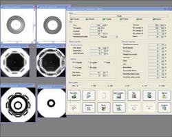
To allow the operator to visualize every stage of the inspection process, the vario2 incorporates a graphical user interface and a 19-in. flat-panel touch-screen monitor. This user interface displays images and results from all the inspection stations as the seals move through the system (see Fig. 2). These include images of the top and bottom surfaces, the outside and outside flipped over, the surface inside, and a high-precision view of the contour of the seal that performs inside and outside dimensional measurements.
To analyze each image as it passes “on the fly” under the various inspection stations, Basler developed its own image-processing algorithms. To check for any defects or voids in the outside or inside of each seal, for example, an area of interest was first set to locate the specific part of each image of interest. By comparing the gray-value deviations, the system determines whether any bright or dark region and, hence, defect is present. Using blob-analysis tools, these imperfections are then categorized and presented to the operator on the touch-screen panel.
Should any defect occur, a reject mechanism directs bad parts into bins for removal. Individual inspection results of each batch are also recorded statistically and by date, providing the operator with the batch CpK and standard deviation of to allow manufacturers to tailor their production process accordingly.


