Rising Star
Ruggedized, high-speed, frame-grabber-based video recording system can monitor shuttle status during launch
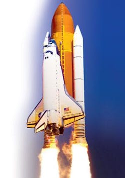
In some extreme environments shock, vibration, heat, and lack of air cooling are the norm. One such place is on-board the space shuttle, and it is here that NASA (www.nasa.gov) is considering solutions to upgrade one of its existing vehicle video/camera recording systems. The system requirements are high frame rate, imaging from multiple cameras, and recording the video and data to a nonvolatile media that can be recovered and read out.
One use of the system would be to mount the cameras and recording system in the top of the shuttle’s solid rocket boosters and point the cameras back at the vehicle to monitor its health and status, much like the small analog cameras currently installed. This is one of many military and commercial applications that require ruggedization or militarization of a high-speed frame-grabber/recording system. The recording system must tolerate extreme vibration, high G shock, and lack of air cooling, while simultaneously providing high-data-rate recording and storage, despite power loss, over a reasonable time period (see Fig. 1).
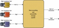
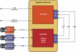
The NASA system requirements include unattended operation and recording for roughly two minutes during liftoff followed by four minutes of recording during the free-fall back to Earth. The camera system will contain one camera operating at Full Camera Link speeds (~500 Mbytes/s) and three Gigabit Ethernet cameras, each operating at up to 75 Mbytes/s, for a total of 725 Mbytes/s. The recording must be nonvolatile as the system will lose power before recovery.
Furthermore, the system must tolerate power loss and power return and restart recording until power is lost at the end. It must have enough memory to record for six minutes, or at least 270 Gbytes of memory. Also, the system must be able to control the cameras to compensate for the varying lighting during the recording. During recording extraction after recovery, the system must support multiple methods of extraction and various computers that may not use the same operating system (see Fig. 2).
In summary, the desired recording system should be rugged or militarized to tolerate vibration and shock at high G forces (preferably non-mechanical) and be able to record multiple hundreds of megabytes per second over an extended period (minutes). In addition, it must store and retain data despite power loss, provide camera control, and have the ability to downloaded data afterwards via common data interfaces (GigE or USB 2.0) to computer systems running any operating system without the installation of special software.
Nonvolatile recording and storage
When NASA contacted Alacron to determine the suitability of any of its products to provide part or all of a solution to these system requirements, Alacron had developed a data-recording system for a previous customer that satisfied similar requirements. The original challenge was to develop a rugged VME-form-factor frame-grabber/recording system that provides the best characteristics of solid-state recording, without the extra overhead and disadvantages of disk drives, disk controllers, disk protocols, and disk drive bulk in a ruggedized board level product.
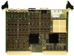
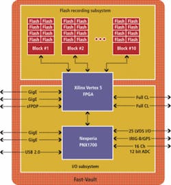
The Alacron product, called Fast-Vault, is a combination of two on-board systems into a 6U VME-form-factor board; a high-speed, 320-Gbyte flash memory system; and an I/O subsystem that provides interfaces to multiple Camera Link and GigE cameras, along with analog and digital inputs (see Fig. 3). The Fast-Vault memory system is organized as an array of ten 80-Mbyte/s recording blocks, each containing two chains of four flash memories operating at 40 Mbytes/s. The complete system contains 80 flash chips, each containing 4 Gbytes of Micron flash memory. The recording blocks do striped recording overlapping data writes with data transfers. The recording blocks are striped by a Xilinx Virtex 5 FPGA, which provides an average recording rate of more than 800 Mbytes/s to the I/O system.
Writing to the flash system is performed with a write leveling algorithm to increase the life of the flash chips, error correction coding, and a defective page substitution list to prevent data loss during recording. The front-panel connectors support one Full Camera Link interface, two Gigabit Ethernets ports, and a LVDS I/O connector. Analog inputs and serial I/O are connected to P2, with two Gigabit interfaces, and the second Full Camera Link interface on the P0 connector. The VME bus is not used by the Fast-Vault; only its power is used.
The on-board I/O system contains four Gigabit Ethernet ports, a serial front-panel data port interface, two Full Camera Link interfaces—which can be split into various configurations down to six Base Camera Link configuration—16 single-ended channels of 200-kHz analog-to-digital converters with ±10-V inputs, and 25 LVDS input or output bits. The I/O system is controlled by a NXP Nexperia PNX1700 processor. The on-board I/O system supports extraction of the data from flash to Gigabit Ethernet or USB 2.0 (see Fig. 4).
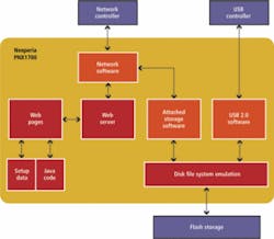
The software architecture of the system is a Nexperia PNX1700 application. The PNX1700 supports a Web server for configuration and control, allowing the recording system to be configured from any workstations running any operating system. Internally the Fast-Vault uses PSOS, which is not exposed to the user. The system operates as a network appliance that records high-speed data sources such as video from high-resolution fast cameras, slower GigE cameras, and various analog and digital sources.
During data extraction the Fast-Vault appears as a USB disk drive or network attached storage. The PNX1700 presents the recordings in flash as a file system that contains files of the flight recordings. These files can be uploaded to the network as raw files, or, in the case of image recording files, can be converted to AVI or MPEG files using a Java application, and downloaded from the embedded Web server to a user’s computer (see Fig. 5).
Prototype
The proposed Alacron solution includes two Fast-Vault boards—one without flash memory. The second board provides frame grabbing, camera control, and information extraction from the images before posting them to the second Fast-Vault board used as a recording system. As the system must operate autonomously, the proposed solution to the NASA application requires the system to start a script at power up and wait for a signal to begin recording and executing the timed events in the script. When the launch system switches to internal power a possible brief power failure can occur, which the system must tolerate.
The recording system executes a script and monitors inputs adjusting camera exposure and frame rate during the various phases of the liftoff. Various cameras are being considered, such as the Silicon Imaging SI-1920HD, Mikrotron MC1311, and Prosilica GC Series Models GC650 and GC660. Also, the latest cameras using GigE and Camera Link standards are being considered.
After the flight, the recording system is recovered and connected to a network, and recordings are extracted. Java applets, running on the user’s workstation, convert the data from raw format to AVI, MPEG, or custom formats. The Java code is obtained from the embedded Web server of the Fast-Vault. The formats of the raw files are open so customers can convert them as they require. All data are time-stamped, and the system supports input of IRIG-B or GPS for absolute time stamping (see Fig. 6).
The proposed Fast-Vault solution provides for all of the requirements of this NASA imaging application. While this is no guarantee that this solution will be adopted by NASA beyond the prototype stage, it does fulfill the basic requirements of a shuttle recording system. Additionally, this solution can be modified to perform equally well in many other challenging airborne, space, ocean, or land-based applications.
Joseph Sgro is CEO of Alacron, Nashua, NH, USA; www.alacron.com.
null

