Off-line system measures screw parameters precisely
Andrew Wilson, Editor, [email protected]
In many companies, 100% inspection of products may not be economically feasible because of the low cost and high volume of the products produced and the expense of developing high-speed inspection systems. Instead, in many companies that manufacture large quantities of products such as threaded fasteners, batch inspection is used as an alternative to determine whether these products conform to specific criteria.
“To perform batch inspection on fasteners,” says Jim Linhart of Jerhen Industries (Rockford, IL, USA; www.jerhen.com), “an operator selects a part from a batch and, using calipers, measures the head diameter, height, length, and major and minor screw diameters.” The details of these measurements are then recorded and, should they start to vary over time, the manufacturing process can be readjusted to maintain the correct parameters. “Of course,” says Linhart, “this process is time consuming and prone to operator error as measurements may vary from one operator to the next.”
Such a problem was faced by quality-control engineers at a major fastener manufacturer in Illinois, where every two hours a batch of 20 parts was taken from a production lot and manually measured. To automate this process, Linhart and his colleagues at Jerhen Industries designed an automated PC-based system based on a smart camera, with off-the-shelf lighting and software.
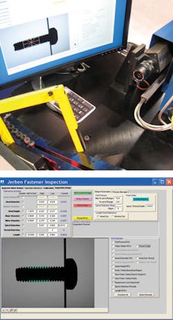
In operation, a fastener is placed on a custom-built slide on which it travels downwards at 30°. As the screw passes in front of a 5 × 2 in. LED backlight from Advanced Illumination (Rochester, VT, USA; www.advancedillumination.com), it triggers a through-beam sensor from Banner Engineering (Minneapolis, MN, USA; www.bannerengineering.com). The output of this sensor is then detected by a custom I/O interface that is used to activate an Impact T27 smart camera from PPT Vision (Eden Prairie, MN, USA; www.pptvision.com) fitted with a 50-mm lens.
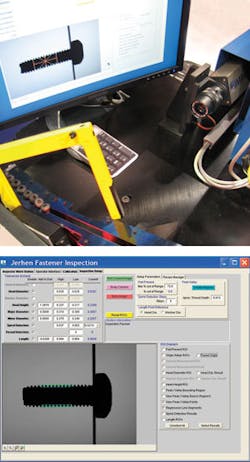
To program the system to perform specific measurements, Linhart used PPT’s Vision Program Manager (VPM), a suite of software with more than 100 inspection tools embedded in the T27 camera. “Before any measurements can be taken,” says Linhart, “an origin tool within the VPM determines whether a part is present and its orientation.” Essentially, this tool determines whether a specific blob (or mass) is present in a predetermined region of interest in the image’s field of view. Once determined, a point of reference is calculated from which other measurements can be made.
After this reference is calculated, a second region of interest is placed over the thread of the screw. Thresholding the image can then be used to determine the peak and valley points of the screw thread. Once the peaks and valleys are known, regression lines are calculated along the peak to peak and valley to valley points and overlayed onto the image. Using these lines, the major diameter (the distance from point to point or the thread) can be determined in multiple areas of the fastener.
To develop a graphical user interface for the system, Linhart used PPT Control Panel Manager (CPM) software, also supplied with the smart camera. Using this interface, the operator can call a preprogrammed recipe by part number. Within 22 ms, the system calculates the head height, major and minor diameters, and thread pitch of the screw; these results are compared with known good data stored in the system.
Should any part fail inspection or present the operator with out-of-tolerance data, the user interface notifies the operator of any measurement error that has occurred. Because the system is PC-based, data can be stored in an Excel spreadsheet and used to provide trend data for the machine-control process.

