High-speed vision system ensures product quality
Off-the-shelf components and software and customized algorithms inspect hygienic products.
By Martin Balog
Sanitary products for personal consumption, such as feminine-hygiene products and diapers, require high-quality material and production processes. In the past, inspection of the production process has been performed by randomly selecting products that are then manually examined in a laboratory. Increasingly, manufacturers are coming to rely on automated inspection systems based on machine vision.
Satisfactory inspection of sanitary products imposes stringent challenges on the vision system. First, the capacity of one assembly line is usually more than 1000 pieces per minute, or 20 or more pieces per second. Another challenge is the necessity of inspecting at several locations on an assembly line, as the products are relatively complex and problems may also occur within internal layers. In addition, the materials are mostly white nonwoven textiles and foils, which complicate the ability of the vision system to recognize all the necessary details of a product and differentiate errors.
System Design
Our design of the TIViS inspection system for feminine sanitary towel production was based on system requirements imposed by the customer. In particular, this meant high-speed inspection-more than 1000 pieces per minute. The next demand was for high reliability, requiring a high degree of certainty in identifying defective products while preserving a minimum of false alerts that increase the percentage of waste in production and represent a financial loss to the customer (see Fig. 1).
Crucial for the customer were requirements for data acquisition and statistical processing, evaluation of undesirable events, and reporting options. On the whole, the system was based on open architecture so as to enable the incorporation of future requirements and expansion into other applications.
To develop the system, we pursued a PC-based solution, using National Instruments LabVIEW because of its openness and ability to apply a range of functions from other areas-for example, data acquisition, graphical presentation, statistical processing, and reporting. LabVIEW enables considerable flexibility in creating a graphical user interface, which enabled the design of a comfortable, transparent, and fast application.
The internal structure of the application was based on the framework that Datalan designed and has implemented within the majority of its complex machine-vision applications. The framework guarantees basic functions such as data flow, image acquisition, synchronization, data acquisition, statistical analysis, SPC, and data presentation in real time. The system provides the customer with simple and transparent data control and processing.
It was necessary to acquire images of the inspected products at two different locations on the assembly line. The first location inspects individual layers and cores that form final products before they are cut out from a continuous strip of material. The second inspection location is just before the final products are packaged into foils. Defective products are removed by an air jet before packaging.
Hardware Components
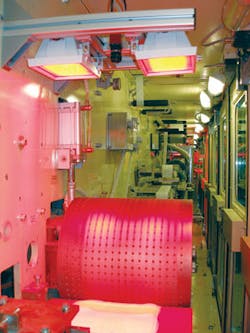
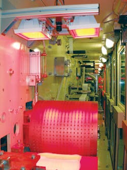
For image acquisition we used two Allied Vision Technologies (AVT) Guppy 046B cameras with 782 × 582-pixel resolution on a 1/2-in. CCD chip. A big CCD chip is primarily useful for providing a shorter working distance when acquiring images of products because the assembly line had limited space availability. These cameras also ensure sufficient image-acquisition speed (53 frames/s) even when the potential speed of the line is accelerated to more than 20 pieces per second. Image acquisition is controlled via external trigger signals from an FPGA on an NI PCI-8254R card. This provides for maximum stability and accuracy of product positioning for image capture (see Fig. 2).
The illumination system required considerable time and effort to design. After consideration of alternate light sources, we selected custom red LED panels. These provide a maximum possible contrast to the selected material and represent one of the key elements to achieving high reliability in quality assessment.
An NI PCI-8254R card was used to synchronize the machine-vision system and main controlling PLC of the assembly line. A big advantage of using this card proved to be the combination of TTL and optically isolated digital inputs and outputs. TTL signals are used as an external trigger for AVT digital cameras. On the other hand, we use the isolated channels when communicating and synchronizing with the PLC, as required by the customer. The most substantial benefit of the PCI-8254R card is the built-in FPGA. This technology can fully cover the requirements for the management of image acquisition and real-time synchronization with a PLC.
The remainder of the system did not require any special components or major modifications of the customer’s existing assembly line. The mechanical holders for the cameras and lights were made of aluminium. Thanks to an optimal distribution of vision components and the primary PC, the system did not require more than 10-m-long cabling, which enabled us to use standard data FireWire 1394a cables and I/O cables for the external trigger of the cameras. The overall application is managed from a IBM/Lenovo PC with the Pentium D 945 processor and 1-Gbyte RAM, which provides sufficient performance for all image-processing and defect evaluation algorithms.
Tracking/Synchronization
Tracking control plays a key role in the system and provides exact monitoring of each inspected product. The tracking control must be able to react to smooth changes in the speed of the processing machine and its maximum speed, as well as provide the required camera synchronization via an external trigger. All of this must be accomplished on a real-time basis.
The system of tracking control for TIViS was implemented in an FPGA on the NI PCI-8254R card via NI LabVIEW FPGA Module 8.20. The basic input signal is in the form of information indicating that a new product to be inspected is positioned at the first camera. The product is recorded in the system under a unique ID. The tracking control system then uses the setup delay for the image acquisition initiation of the first camera. The system receives a similar signal from the PLC in the second camera position. Thanks to the information about the distance between these two positions and the speed of the processing machine, the system can identify when a product is located at the second camera position.
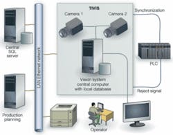
Image acquisition is again synchronized in terms of hardware via the external trigger of the camera (see Fig. 3). The results from the inspection of each camera are subsequently combined, and with one unique ID, sent to the FPGA. When the tracking control returns the result from the inspection to a main control PLC of the assembly line, a reject signal is sent for those products that fail the quality criteria. Considering the high speed of the assembly line, the accuracy of the reject signal timing is crucial to prevent false air-jet removal of defect-free products that may be near the defective product.
The tracking control program runs on an FPGA in several parallel loops that enable an immediate response to input signals and thus provides for a real-time flow. Thanks to asynchronous communication with the main application, which is running under Microsoft Windows XP Professional SP2, it does not have to meet the parameters of a real-time application and may be optimized with respect to overall performance.
DEFECT DETECTION
A specific approach had to be applied in the development of algorithms to evaluate product parameters and detect individual defects. First, the process runs at high speed (up to 2 × 20 images per second). More important, many parameters require complex image processing. Thanks to the mostly white materials used, the details on each image have a very subtle contrast and can only be identified with difficulty. It was necessary to design optimized algorithms for certain areas, because the results could not have been attained using standard machine-vision tools.
The first step in the design of the image-processing concept was the optimization of illumination. The LED lighting enabled us to attain a sufficient increase of contrast on key positions of the products--for example, wings and individual product cores. Without this optimization it would be impossible both to evaluate some characteristics and to identify critical types of defects that must be eliminated from the final production.
Algorithms were tailored for each camera. This was carried out in several iterations. For the general prototype of image processing, we used the NI Vision Assistant 8.2.1 application that is part of the company’s Vision Development Module (VDM) 8.2.1. With such a complex evaluation of many parameters, the standard functions and operators from libraries failed to produce an adequate output. Additionally, customized algorithms for certain parameters had to be developed-for example, the assessment of the bending of wings. In this case, an adjusted version of a Hough Transformation was used to identify a low-contrast edge of wings against background material and evaluates its location, length, and angle.
A large group of algorithms was rewritten in Visual C++ language into the DLL library. In addition to its own source codes, the OpenCV and IPL 2.5 libraries were used in the development phase. They implement some necessary low-level algorithms optimized for Intel Pentium processors. Several evaluation and image-processing functions were also attributed to the libraries from VDM 8.2.1, in particular pattern matching and some gauging functions.
By combining parts of LabVIEW and C++ libraries we could develop very reliable and high-performance algorithms that fully evaluate the product parameters.
User Interface
As the overall application is implemented in LabVIEW (except for some algorithms), the programmers could customize a user interface. The interface mainly provides for functions such as image visualization, visualization of computed values and statistical quantities, setting of inspection parameters for individual product types, and system settings of the overall application. This interface was designed to be ergonomic and easily manageable.
The main screen is divided into several parts that address a certain area of use: Online, List of Articles, and Setup of Articles. Moreover, it is possible to enter the system settings of the application and FPGA. Several control components and basic information about the status of the application are always displayed in the upper part of a window.
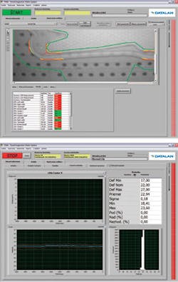
Online includes the image display of products as well as results and statistical values. They provide a comprehensive summary of the inspection and presence of defects. A useful function is the switching between the display of each product and display of images of the last defective product. As there are not so many production defects, the operator can continuously monitor the images of defective pieces and thus acquire an overview of the production status. The computing results are displayed in different ways: a table, a graph of actual values for a certain period of time, or a graph of time-based error rate (see Fig. 4).
The List of Articles helps establish a database of various setups for different types of products. Whether completely different products are inspected or only different setups and variants of the same product for different customers, TIViS enables the user to define an unlimited number of items. Following the initiation of the inspection, the correct article may be simply selected (automatically or manually), and the operating staff does not have to laboriously set up each parameter.
Setup of Articles defines specific setups of processing and evaluation of individual computed product parameters. Each setup is well arranged and interactive. It can work in online and offline mode. In the online mode, the actual image from the assembly line is taken three times per second, and its parameters are calculated based on default values. This enables operators to change setups in real time without directly impacting ongoing production. If an operator is satisfied with the change of parameters, they may apply them, and immediately all products will be inspected according to the modified configuration. If the operator does not apply the changes, the initial settings remain effective. Offline mode enables the setup of an arbitrary item with the use of images saved in the database on the hard disk. It is also possible to perform such a setup while the inspection system runs at full capacity in the background.
TIViS was designed to fulfill demanding requirements and provide added value in the form of visualization tools and data processing and archiving. Our philosophy is to offer an optimized solution for all customers, especially by developing custom algorithms for each type of products. The open system design enables further enlargement and added functions for new products, as well as managing manufacturing processes, statistical process control, monitoring and signalling of risks, and integrating other information systems.
Martin Balog is a consultant and project manager responsible for machine-vision applications at Datalan, Bratislava, Slovakia; www.datalan.sk.
null


