Fundamentals of Imaging Lenses
Machine vision, or imaging, is a fast-growing field. Engineers in numerous disciplines—such as factory automation, autonomous systems, life sciences, aerospace, and logistics—are creating vision systems to help fulfill automation objectives.
Choosing the correct lens is an important step in system development. To help navigate this process, this article describes how to select an appropriate lens.
Defining Requirements for a Machine Vision System
The first step in choosing a lens for a machine vision system is to define the requirements for your application. The two parameters that drive selection are the working distance and field of view. The specific definitions for these parameters are:
- Working Distance (WD)—The distance from the front or first surface of the lens to the object under inspection.
- Field of View (FOV)— The viewable area of the object under inspection. This is the portion of the object that fills the camera’s sensor. This area is commonly reduced to horizontal (HFOV) or vertical (VFOV) dimension for ease of calculation.
When specifying an entire FOV (Horizontal by vertical dimension or HxV), keep in mind that the typical machine vision sensor will have a 4:3 aspect ratio (ratio of width to height). That is why you should define the critical parameter of the FOV (either horizontal or vertical) and use that for the calculations described in this article.
After defining the WD and FOV, the next parameters to specify are the sensor size and required resolution.
Sensor Size
The size of a camera sensor’s active area is typically specified as a fractional inch or decimal such as 1/1.1 in, 2/3 in or 1.2 in.
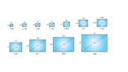
It is worth noting that this nomenclature is in reference to the sensor equivalent of an analog tube; while this is no longer relevant, it is still the given specification for the vast majority of sensor manufacturers. The important parts of a sensor’s active area are horizontal and vertical measurements (for determining FOV) and diagonal dimension of the sensor (for determining compatible lenses).
Resolution
The resolution is the minimum feature size of the object that can be distinguished by the imaging system. Resolution is more accurately described as spatial frequency, measured in line pairs per millimeter (LP/mm).
To determine the appropriate resolution, define the size of the minimum feature that is required to be resolved for the application and then define a pixel count for that feature, which will depend on the goal of your application. While there is no concrete definition for how to select pixels per feature and the only true way to know if your resolution is adequate would be to test it, you can find some general benchmarks below.
| Pixels per Feature | |
| 3 | Detection |
| 4 | Orientation |
| 10 | Recognition |
| 16 | Identification |
This can then be used to determine the minimum pixel size and convert it to LP/mm.
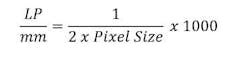
While this information is not required to determine the size of the lens, you will use it to determine the quality of the lens necessary for a particular application.
Additional parameters that should be considered are Depth of Field (DOF) and environmental requirements, such as IP rating, vibration tolerance, or athermalization. The Depth of Field is the maximum object depth that can be maintained entirely in acceptable focus, which is typically expressed as +/- X.X mm.
How Lens Parameters Relate to Those Requirements
Now that you have all the required specifications for a lens, calculate the required Focal Length (FL). This can be approximated using the following expression:
FL= (H x WD) / HFOV
Where H is the horizontal measurement of the sensor, WD is the working distance and HFOV is the horizontal measurement of the field of view. If using the vertical dimension as the critical measurement, simply replace the horizontal measurements with the vertical measurements.
This will output the approximate FL required for your HFOV and WD. Keep in mind that FLs are relatively standardized across different manufacturers. For instance, if your approximate FL is 19.7 mm, you would be unlikely to find a direct match, so this number will either need to be increased or decreased depending on the flexibility of the system.
As illustrated in the expression above, FL and FOV are inversely proportional to one another. For example, if you assume the HFOV used in the equation above is the minimum requirement for your vision system, you want to select a FL one step below the approximate value to increase your FOV—in this case moving from 19.7 mm to a more standard 16 mm lens.
From here, you can select a lens with the required FL to cover the sensor that you will use in the application. Be mindful of how large of a sensor the lens covers. If you select one too large, you may spend more money than necessary. But if you select one that is too small, it will not cover the sensor and vignette (defined below).
- Vignette—When light rays do not make it through the entire lens system to the sensor because they are blocked by the edges of individual lens elements or mechanical stops.
From here, you can analyze the specification sheet to determine whether the lens will handle the parameters defined in the previous step. If you cannot find the relevant information for your WD/FOV requirements in the generated specification, reach out to the manufacturer to get those curves, or if you have access to optics software, request the prescription.
Key Lens Parameters
Now that you’ve selected a lens, read its performance curves to insure it meets the needs of the application. The first and most important curve is the modulation transfer function curve (MTF), which is defined below.
Modulation Transfer Function
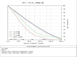
Modulation Transfer Function (MTF) is an information-dense metric that reflects how a lens reproduces contrast as a function of spatial frequency (resolution).
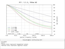
This figure provides the percentage contrast vs. the spatial frequency at a given point on the sensor chip. The general rule of thumb for the minimum required contrast for machine vision purposes is 20%. This leads us to generally define lens performance as the spatial frequency at 20% contrast. From this graph, we can extrapolate that our worst field (in this case the 8 mm corner of our chip) has approximately 175 lp/mm at 20% contrast in image space, meaning on our image sensor. To convert this to object space, we would simply multiply this by the magnification of our lens.
Depth of Field
Depending on the needs of your application, you may also be interested in the DOF of the lens at your given WD and f/#. Below is an example curve for a lenses DOF:
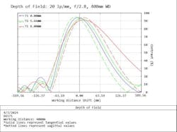
Much like the MTF curve, our y axis is Contrast. However, the x axis of a DOF curve is instead the working distance shift. The 0.0 point on this curve is the point of best focus, moving +/- along the x axis is the depth at which your image will remain in focus. This is defined at a specific resolution requirement—in this example 20 lp/mm—and typically defined at 20% contrast.
If the given DOF is not sufficient, it can be increased by increasing the lens’ f/# (pronounced “F-number”). The definition for this parameter can be found below:
- f/#—Setting on a lens that controls overall light throughput, depth of field (DOF), and the ability to produce contrast at a given resolution.
The effects of altering the f/# is summarized in the table below, where the top row shows if that parameter increases / improves (Ʌ) or gets worse / decreases (V) as f/# either increases (Ʌ) or decreases (V).
|
f/# |
Diffraction Limited Resolution |
Depth of Field |
Light Throughput |
Numerical Aperture |
|
Ʌ V |
V Ʌ |
Ʌ V |
V Ʌ |
V Ʌ |
Lenses with lower f/#s are considered fast and allow more light to pass through the system, while lenses of higher f/#s are considered slow and feature reduced light throughput. Here is an example of the same lens used previously running at f/8.0 instead of f/2.8:
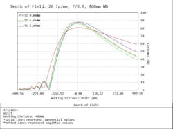
As you can see, the simulated working distance shift is significantly larger when compared to the previous figure (2-3X more DOF). However, the resolution is slightly lower.
As the f/# is progressively increased, you will see the same thing occur. Finding the appropriate balance between resolution and DOF should be determined on an application-by-application basis.
Common Pitfalls
One of the most common pitfalls in designing a vision system occurs when you do not save enough space for the lens and camera. Typically, most lenses have a minimum working distance of 100 mm for moderate focal lengths (8-25 mm) and up to 750-1000 mm for longer focal lengths. The general rule of thumb is to save a 4:1 ratio of WD:FOV. This is not a catch-all solution but using it as a benchmark can help avoid headaches down the road. A good machine vision lens can be expensive but not as expensive as a fully custom solution.
Conclusion
Choosing a lens can be a daunting task if you do not have somewhere to start. This can be a nuanced decision and sometimes requires trial and error in a lab environment. If you are ever faced with trouble in making the correct lens solution, reach out to your imaging lens supplier for guidance and recommendations.
About the Author

Christopher Razze
Christopher Razze is a machine vision sales engineer at Edmund Optics (Barrington, NJ, USA.).