APPLICATION-SPECIFIC integrated circuits TARGET MPEG COMPRESSION
APPLICATION-SPECIFIC integrated circuits TARGET MPEG COMPRESSION
By Andrew Wilson, Editor at Large
Just as image-processing vendors embraced video-broadcast standards for interoperability among cameras, frame grabbers, and displays, integrated-circuit (IC) vendors are now incorporating video-broadcast compression standards into application-specific integrated circuits
(ASICs). With this increased capability, compression products that have up until now used proprietary, wavelet, or JPEG (Joint Photographic Experts Group) methods are turning to MPEG (Moving Picture Experts Group) standards. As this transition takes place, video storage and surveillance systems are moving into the digital realm by compressing video data on rewriteable optical drives.
Established in 1988 with the mandate to develop standards for the coded representation of moving images, the MPEG has produced two standards to date: MPEG-1 and MPEG-2. Whereas MPEG-1 was developed to encode progressive image sequences at a 1.2-Mbit/s data rate suitable for compact-disk (CD) video applications, MPEG-2 can be used to encode both progressive and interlaced video.
With the emergence of the MPEG-2 standard, many vendors developed hardware- or software-based encoding packages that compressed video in digital format. Once compressed, MPEG-2 video can be replayed using a number of off-the-shelf MPEG-2 decoders from vendors such as Sony Semiconductors (San Jose, CA), Toshiba (Irvine, CA), and Zoran (Santa Clara, CA). Although software-encoding packages can provide MPEG-2 compression, they generally do not operate at real-time video rates.
After the emergence five years ago of the MPEG-2 standard, hardware vendors have also developed relatively expensive real-time compression engines. Now, with the decreasing linewidths available on silicon chips, greater functionality can be incorporated on chip, and many silicon foundries are offering MPEG-2 encoders as multiple- or single-chip solutions.
Profiles and levels
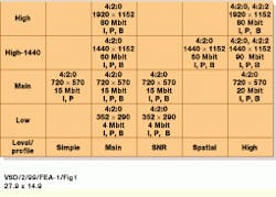
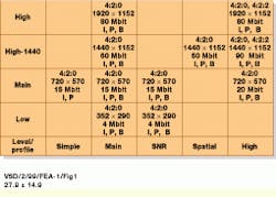
Although the MPEG-2 specification can, in theory, encompass bit rates as high as 400 Gbits/s and images as large as 16k ¥ 16k pixels, a system of profiles and levels has been applied to the standard to make it useful in practical applications (see Fig. 1). In implementing MPEG encoders and decoders, vendors can specify their ICs as operating at a number of profiles and levels. These include Main Profile at Main Level (MP@ML), Simple Profile at Main Level (SP@ML), Main Profile at High Level (MP@HL), and 4:2:2 at Main Level (4:2:2@ML).
To be compliant with the MPEG-2 standard, however, MPEG-2 decoders and encoders do not have to be comparable. Because the specification allows for scalability, inexpensive decoders can be used that allow only portions of the video bit stream to be decoded; however, these portions would provide a lower quality than those provided by the more-expensive, higher-quality devices. Today, most currently available MPEG-2 encoder ICs comply with the MP@ML standard.
Unlike JPEG or M-JPEG compression that use spatial techniques to compress images, MPEG-2 uses both spatial and temporal redundancy to reduce the amount of information in a video stream. Thus, implementing MPEG-2 on multichip or single-chip solutions was, until now, not possible because of the large number of functions required to implement MPEG-2 encoding.
In accordance with MPEG-2, video streams conform to a layered coding structure that consists of image sequence, group of pictures (GOPs), picture, slice, macroblock, and block layers (see Fig. 2). Whereas the video se quence contains controls and parameters of the sequence, the GOP layer`s size is determined by the quality and compression required. In the GOP layer, three different picture types are allowed. Although intraframe (or "I") pictures are compressed independently of each other using discrete cosine transform (DCT) and run-length-encoding (RLE) methods, they serve as reference or anchor frames for interframe compression based on temporal redundancy.
Motion compensation
Because most pictures in an image sequence are correlated, motion compensation removes the redundancy among them. To perform this motion estimation, the picture is divided into 16 ¥ 16-pixel macro blocks, and a search is performed to determine their positions in a subsequent frame (see Fig. 3).
In MPEG-2, this motion estimation is performed on each luminance macroblock. Once a relatively good match is found, the MPEG-2 encoder assigns motion vectors to the macroblock that indicate how far horizontally and vertically the macroblock must move to make this match.
While rapidly moving images may require a motion-vector range of 䕤 integer pixels, slower moving images may only need a 䔴 range. However, because motion tends to be more prominent across the screen in a horizontal direction, rather than in a vertical direction, a greater horizontal search range (motion-vector radius) is more practical than a vertical search range.
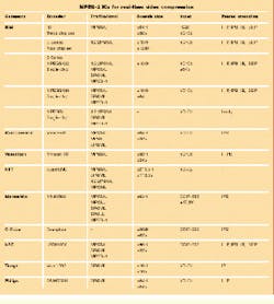
In the more than ten ICs now available for performing MPEG-2 compression, most feature larger horizontal than vertical search sizes (see table on p. 37). Some devices from iCompression (Santa Clara, CA) and Visiontech (Herzliya, Israel), for example, use 䕤H/32V and 䕖H/34V search sizes, respectively. Other devices, such as the SuperENC from NTT (New York, NY), use a larger motion estimation search area of 𫐻.5H/113.5V.
According to NTT, improving video quality requires that motion be detected at high precision, thereby necessitating high computational throughput. To achieve this, the SuperENC uses a Look-Neighbor-First-Search method that selectively employs a wide-area search or a proximity-area search and an area-hopping technique that improves the tracking of high-speed motion. Together, they allow motion to be detected accurately with minimum searching and reduce the number of computations required for motion detection.
Encoding images
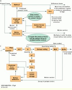
In typical MPEG-2 encoder implementations, images are first presented to the encoder in YCbCr color space in either 4:2:0 or, optionally, 4:2:2 chroma format. After an anchor frame has been computed using DCT/RLE encoding, motion vectors are computed to best predict the present frame. In such designs, a frame store holds a predicted frame that has been constructed using the previous frame and motion-vector information (see Fig. 4). The present picture is then subtracted from the predicted present picture and the difference output. Although the MPEG standard allows for predicted (or "P") frames to be computed from I-frames, it also allows images to be determined bidirectionally. Such "B" frames are coded using motion compensation from both past and future anchor pictures.
The P-pictures provide better compression than the I-pictures do because they accommodate spatial redundancy and redundancy between previous frames. In addition, they can act as anchor frames in the predictive process. Although B-pictures provide the best compression, they are not used as anchor pictures because of errors that would be introduced in the coding process. And, because both a future and an anchor image must be loaded to encode and decode B-pictures, both the coding and the display order are different.
The main advantage of using B-frames is coding efficiency because using B-frames results in fewer bits being coded overall. Quality also can be improved where moving objects reveal hidden areas in video sequences. In such cases, backward prediction allows the encoder to better decide how to encode the video within these areas. And, because B-frames do not predict future frames, any errors generated will not propagate further in the sequence.
In the MPEG-2 standard, the developer can chose to arrange picture types in video sequences to suit different application requirements. "As a general rule," says Thomas Sikora, chairman of the MPEG Video Group at the Heinrich-Hertz-Institut Berlin (Berlin, Germany), "a video sequence that is coded using only I-pictures (I, I, I, I, I, I,...) allows the highest degree of random access and low compression rates." A sequence coded with a regular I-picture update and no B-pictures (I, P, P, P, P, P, P, I, P, P, P, P, . . . ) achieves moderate compensation and a certain degree of random access.
"Incorporation of all three picture types (I, B, B, P, B, B, P, B, B, I, B, B, P, . . . ) may achieve high compression and reasonable random access, but also increases the coding delay significantly," adds Sikora. Although there is a limit to the number of consecutive B-frames that can be used on a group of pictures, most applications use two consecutive B-frames (I, B, B, P, B, B, P, . . . ) as the ideal trade-off between compression efficiency and video quality.
One disadvantage of using B-frames is that the frame-reconstruction-memory buffers used within the encoder and decoder must be doubled in size to accommodate the two anchor frames. In addition, there will be a delay throughout the system as frames are delivered in an out-of-order sequence.
Computational complexity
Because of the computational complexity, bandwidth, and buffer size associated with B-picture generation, some MPEG-2 encoder vendors have decided to optionally include this feature as part of their IC offerings. In the implementation of its MPEG-2 (IPB) encoder chipset, for example, IBM Microelectronics (Fishkill, NY) has developed a three-chip set that can perform MPEG-2 compression as either a one-, two-, or three-chip system.
As its base encoding IC, IBM`s I-device (MPEGSE10) is required in all three IC configurations. In a one-chip configuration, this IC can operate over an 8-bit address/16-bit data bus to produce only I-encoded pictures. Alternatively, system developers can use the company`s Refine or R-device (MPEGSE20) and Search or S-device (MPEGSE30) to build more-complex encoders. In a two-chip configuration, the I- and R-ICs operate together to produce I-P-encoded pictures. Because I-P-encoded pictures require fewer bits to encode compared with I-only pictures, the resulting bitstream can be transported at a lower bit rate.
In a three-chip configuration, I-, R-, and S-ICs can be used to produce I-P-B encoded pictures. This results in a lower number of bits needed compared to either I- or I-P encoded pictures. According to IBM, the chipset can be used to encode standard NTSC MPEG-2 video using the i960 microprocessor from Intel (Santa Clara, CA) and video digitizing ICs, such as the 7111 from Philips Semiconductor (Sunnyvale, CA) or the 819A from Brooktree--now Rockwell Semiconductor Systems (Newport Beach, CA).
Evaluation boards
To speed integration of their MPEG-2 encoders, many IC vendors offer evaluation platforms or boards that incorporate the peripheral video decoder, memory, and input/output (I/O) devices required to develop complete video-encoding solutions. Although both NEL (Tokyo, Japan) and iCompression (Santa Clara, CA) have chosen the PCI bus for operation with their video encoders, Visiontech (Herz liya, Israel) has instead chosen to offer its reference design on a smaller stand-alone board.
NEL`s board-level offering, the Reimay RM200, is a PC-based board that can be used to encode NTSC or PAL video. Developed jointly by NEL and NTT (New York, NY), the Reimay board runs under Windows 95/98/NT 4.0 and is supplied with GUI-based scene editor and control software that allows developers to automatically create MPEG-2 video files.
Like the NEL board, the Vivace izC board from iCompression occupies a single PCI slot and runs under Windows 95. In addition to a PCI interface, the board supports both standard serial- and parallel-encoded data outputs. In operation, the board delivers an MPEG-2 video stream and can be programmed with variable bit rate; number of macroblocks, I-, P-, or B-frame encoding method; and dc coefficient precision.
Rather than choose a standard bus and operating system, Visiontech`s Mvision 10-104 real-time video encoder is implemented on a 3.8 ¥ 3.6-in. stand-alone board. Based on the MVision10 MPEG-2 encoder jointly developed by Visiontech and CSK (Tokyo, Japan), the board is capable of encoding NTSC and PAL video using I-, P-, and B-pictures at D1 (720 ¥ 480-pixel) resolution.
Although other IC vendors have yet to produce board-level products, it seems certain that they will offer reference designs. And, in applications for which large amounts of video must be stored, it is likely that these MPEG-2 encoder products will displace proprietary, M-JPEG, and wavelet-based encoding techniques as the compression standard of choice.
FIGURE 1.Although the MPEG-2 standard encompasses 400-Gbit/s bit rates and 16k ¥ 16k-pixel images, its system of profiles and levels allows use in less-demanding practical applications. Vendors can therefore specify their ICs at a number of profiles and levels that include Main Profile at Main Level (MP@ML), Simple Profile at Main Level (SP@ML), Main Profile at High Level (MP@HL), and 4:2:2 at Main Level (4:2:2@ML).
FIGURE 2. The MPEG-2 video streams conform to a structure of image sequence, group of pictures (GOPs), picture, slice, macro-block, and block layers. While the video sequence contains controls and parameters of the sequence, the GOP layer`s size is determined by the image quality and the compression required. Although intraframe (I) pictures are compressed independently using discrete cosine transform (DCT) and run-length-encoding (RLE) methods, they serve as anchor frames for temporal redundancy-based inter-frame compression. (Courtesy Tektronix)
FIGURE 3.Because pictures in an image sequence are correlated, motion estimation removes the redundancy between them. To do so, an MPEG-2 encoder divides pictures into 16 ¥ 16-pixel macroblocks and performs a search to determine its position in a subsequent frame. Once a match has been found, the MPEG-2 encoder assigns motion vectors to the macroblock that indicate how far horizontally and vertically the macroblock must move to make a match. (Courtesy Tektronix)
FIGURE 4.In MPEG-2 encoders, images are presented in YCbCr color space in either 4:2:0 or 4:2:2 chroma format. After an anchor frame has been computed using DCT/RLE encoding, motion vectors predict the present frame. In such designs, a frame store holds a predicted frame that has been constructed using the previous frame and motion vector information.
