Graphical icons help speed system design
Linking a series of graphical image-processing operators improves the development of image-processing and machine-vision systems.
By Andrew Wilson, Editor
In the past, software packages were offered as a series of C-callable libraries that system integrators used to construct machine-vision applications. While many frame-grabber and camera vendors still offer these libraries, others have chosen to offer graphical imaging blocks that can be linked together to more rapidly build customized software. While this can speed the development of end-user systems, the developer still must understand the nature of the image-processing task to be performed and the building blocks that are required to accomplish the task.
“Employing an icon-based, drag-and-drop environment simplifies developing image-processing applications and eliminates the need for writing code in a proprietary language,” says Chris Martin, product manager at AccuSoft. Many of these software packages offer standard libraries of functions that are represented as graphical icons that can be used in its visual programming environment. “These libraries,” Martin says, “provide the standard functions needed for common tasks, such as image manipulation and enhancement.”
“Software engineers need interfaces that can display all the design information and hide unnecessary information,” says Klaus-Henning Noffz, managing director at Silicon Software. “In this way, the designer can concentrate on the algorithmic construction of the application.”
In many icon-based software packages, the graphical interface is focused on this design flow, which is accomplished using operator icons and connecting links. While the icons represent algorithmic modules, the links represent image data pipelines. Machine-vision and image-processing applications can be created by dragging graphical icons onto a construction area within the program and connecting the icons using links. Parameters of both modules and links can often also be set using list boxes or numeric fields.
A few companies use these concepts to offer programs with callable graphical icons to perform specific functions and linked using a data flow diagram. These include Vision Builder from National Instruments (NI), WiT from Logical Vision, a division of DALSA; The Video and Image Processing Blockset from The MathWorks; VisiQuest from Accusoft; and the Visual Applets package from Silicon Software. All of these packages vary with the amount of functionality and hardware support they provide. Once image-processing applications are developed using the built-in “block-libraries,” C code can be generated and the software ported to the embedded application. While packages such as WiT support flow control logic such as if-then-else or for-loops, many other packages do not support these features.
Hardware support for these packages is also limited to specific devices. Being owned by DALSA, Logical Vision’s WiT, for example, supports most frame grabbers from DALSA, such as the X64, Viper, PC-Series, and Bandit II, as well as DirectShow and TWAIN-compatible devices such as USB and FireWire. Similarly, AccuSoft’s VisiQuest supports the IIDC/DCAM interface and allows FireWire cameras to be used with the glyph-based software.
Filtering images
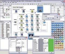
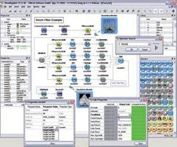
Silicon Software has taken a different approach to the development of its VisualApplets software. VisualApplets is a graphical tool for hardware programming FPGAs on the company’s microEnable III PCI Camera Link frame grabber. A combination of operators and filter modules are combined in a graphical environment and compiled to a loadable hardware applet. These libraries contain operators for pixel manipulation, logical operators for classification tasks, and more complex modules for color processing and image compression (see Vision Systems Design, January 2006, p. 48).
While the operators found in Visual-Applets are perhaps less complex than those of other software packages, the ability to quickly implement functions within an FPGA results in rapid processing speeds. Recently, the company demonstrated how its software could be used to perform a Kirsch filter in four directions (see Fig. 1).
Similar to the Prewitt and Sobel operators, the Kirsch filter approximates the first derivative of an image function operating as a compass operator to determine gradient directions within the image. In this example, the gradient is estimated in four directions. At different points in the design flow, a simulation probe can be used to probe the effects of the image processing operations. After such programs are built, Silicon Software’s synthesis and Xilinx’s place-and-route software convert the hardware design into an FPGA layout that is then integrated, configured, and executed on the microEnable board.
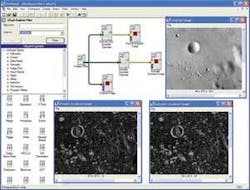
Users of VisiQuest can also leverage the software’s visual programming environment and library of glyphs to create simple or complex vision-system applications. For example, glyphs exist for many types of edge-detection functions (see Fig. 2). Thus, instead of writing these gradient operators in a program, VisiQuest users drag them into the workspace and graphically connect them with other glyphs. In this example, a file stored on the computer is loaded and run through a Prewitt and isotropic gradient operator. These glyphs perform horizontal and vertical edge enhancement which are then presented to the user in an output window.
“Images can be acquired by VisiQuest from a file stored on the host computer, remotely from a relational database, or in real time from an industrial camera,” says AccuSoft’s Martin. “And since VisiQuest uses AccuSoft’s ImageGear product, developers need not be concerned about image format conversion after acquiring an image to begin processing it.”
“With the evolution of intelligent cameras, VisiQuest users are becoming more interested in using the software as a rapid design and prototype solution for image processing algorithms that can be embedded into the camera,” says Martin. “Since VisiQuest features a library of functions and tools to reduce the complexity of testing and debugging, machine vision system integrators can design and deploy a system in a shorter time than is required writing custom software.”
Stepping up
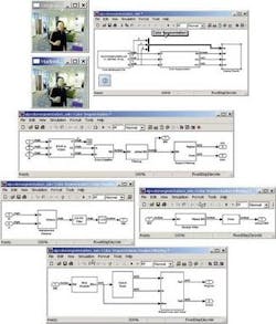
Of course, such packages can be used to perform much more sophisticated image-processing operations. In a demonstration designed to highlight the capabilities of model-based design using Simulink and the Video and Image Processing Blockset, The MathWorks has shown how, using relatively few building blocks, a system can be developed that tracks a person’s face and hand based on color segmentation (see Fig. 3).
To create an accurate color model for the demonstration, many images containing skin-color samples were processed to compute the mean (m) and covariance (C) of the Cb and Cr color channels of a YCrCb image. After converting the image from RGB to YCrCb color space, the Color Segmentation/Color Classifier subsystem classifies each pixel as either skin or non-skin by computing the square of the Euclidian distance between two points (the Mahalanobis distance) and compares it to a threshold as follows:
The result of this process is a binary image, where pixel values that are equal to one indicate potential skin-color locations.
The Color Segmentation/Filtering subsystem filters and performs morphological operations on each binary image, which creates the refined binary images shown in the Skin Region window. The Color Segmentation/Region Filtering subsystem uses the Blob Analysis block and the Extract Face and Hand subsystem to determine the location of the person’s face and hand in each binary image. The Display Results/Mark Image subsystem then uses this location information to draw bounding boxes around these regions.
Providing higher-level building blocks allows more complex systems to be developed in shorter periods of time. Recognizing this, NI demonstrated three of the latest additions to NI Vision Assistant at the Vision Show East (May 9-11; Boston, MA, USA). The Vision Assistant, the company’s vision application prototyping environment, automatically generates ready-to-run LabView diagrams, C++, or Visual Basic code. New features demonstrated included an adaptive thresholding tool, a watershed algorithm, and a golden template-matching function (see Vision Systems Design, April 2006, p. 28).
NI’s Vision software is supplied in two different packages: the Vision Development Module and NI Vision Builder for Automated Inspection (AI). While the Vision Development Module is a collection of vision functions for programmers using NI LabVIEW, NI LabWindows/CVI, C/C++ or Visual Basic, Vision Builder AI is an interactive software environment for configuring, benchmarking, and deploying machine vision applications without programming. Both software packages work with all of the company’s NI Vision frame grabbers and NI’s Compact Vision System.
Oil filters
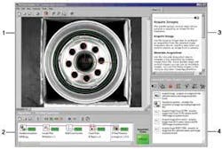
Using Vision Builder AI, simple measurements, such as edge detection, gauging, counting, pattern-matching, and part identification can be used to inspect products such as oil filters to ensure that the correct number of filtration holes are present and the diameter of the rubber gasket is correct. An inspection diagram window displays the sequence of Vision Builder AI steps that comprise the inspection (see Fig. 4).
As the oil filter moves along the production line, it may be shifted or rotated and thus the regions of inspection need to shift and rotate with the filter. For this to occur, a coordinate system must be set relative to a significant and original feature of the oil filter. In this case, the center hole of the oil filter is found using a Match Pattern function and used to form the basis of the coordinate system.
To detect and count the filtration holes within the filter, the Detect Objects step is used. With a region-of-interest (ROI) tool, a ROI can be described that encircles the ring of smaller holes. Vision Builder AI groups contiguous highlighted pixels into objects, depicted by red bounding rectangles. By default, Vision Builder AI returns measurements in pixels that can be mapped into other measurements using a spatial calibration wizard.
To measure the diameter of the gasket, a ROI is drawn across the width of the filter, and a Caliper Step finds the width of the gasket. To deploy the application, Vision Builder AI includes a built-in inspection interface that features a display window to preview the part being inspected with overlays and accompanying text. In addition, a Results panel lists all of the inspection steps, their measurements, and pass/fail information. An Inspection Statistics panel is also provided that gives information useful for quality assurance.
Company Info
AccuSoft
Northborough, MA, USA
www.accusoft.com
DALSA
Waterloo, ON, Canada
www.dalsa.com
Logical Vision
Burnaby, BC, Canada
www.logicalvision.com
National Instruments
Austin, TX, USA
www.ni.com
Silicon Software
Mannheim, Germany
www.silicon-software.com
The MathWorks
Natick, MA, USA
www.mathworks.com
