Snapshots
3-D system inspects railroad tracks
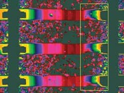
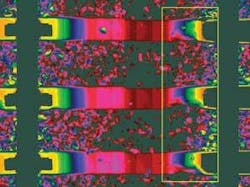
Georgetown Rail Equipment Company (Georgetown, TX, USA; www.georgetownrail.com) required a faster, more efficient method to analyze track and provide a detailed report of track conditions based on an assortment of factors, but principally crosstie conditions. The standard method of track inspection requires a person to walk the track and subjectively grade the condition of wood or concrete crossties and fastener hardware by sight. Georgetown challenged machine-vision integrator Nagle Research (Austin, TX, USA; www.nagleresearch.com) to build a machine that could traveled along the track at speeds of up to 30 miles per hour while analyzing up to 70,000 ties.
Because various chemical treatments applied to wooden crossties stain them and would confuse 2-D analysis algorithms, Nagle Research developed a 3-D system that could be used to gather data regardless of tie discoloration. The company used a Ford F250 track-capable pickup truck, and built a retractable chassis in the bed of the truck to house two Ranger 3-D cameras from SICK IVP (Linköping, Sweden; www.sickivp.com) and laser equipment. The system can scan hundreds of miles of track in one day-with better than 0.08 in. resolution in all axes-and have a comprehensive report on more than two dozen track conditions prepared within 24 to 48 hours.
VDMA sees strong growth
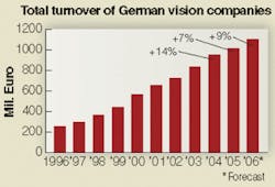
At a press conference in Stuttgart, Dietmar Ley, CEO of Basler (Ahrensburg, Germany; www.baslerweb.com) and chairman of the Machine Vision Group of the VDMA (German Engineering Federation; Frankfurt am Main, Germany; www.vdma.org), described machine-vision market developments in Germany. He noted a projected total turnover among German vision companies in 2006 of €1.1 billion, a 9% increase from 2005. He also noted that, in 2005, 55% of the companies had fewer than 20 employees. Application-specific vision systems constituted 57% of the products sold; cameras constitute 55% of the components sold, with frame grabbers making up 13% and smart cameras an additional 15%.
Exports remain the growth engine of the German machine-vision industry, with 23% of total turnover going to the rest of Europe, 17% to the Americas, and 15% to Asia and the rest of the world. The percentage of total turnover exported from Germany rose from 44% in 2004 to 55% in 2005.
Reel system checks electronic components
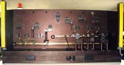
BI Technologies (Fullerton, CA, USA; www.bitechnologies.com) produces a number of surface-mount electronic components on reels containing up to 4000 components. Many of these are glass-covered, which presents special problems in quality control testing. According to Stewart Beveridge, senior manufacturing engineer at a BI facility in the UK, “We had four highly trained people checking the components through microscopes. It took up to an hour to check each reel. The result was not easy to view and tired the inspectors. Faulty components had to be cut from the reel, and if more than seven components were found, the entire reel had to be reprocessed.”
BI called in Envisage Systems (Berkhamsted, UK; www.envisagesystems.co.uk), a company specializing in automated visual inspection systems for the electronic components industry. Envisage, in turn, consulted with Multipix Imaging (Petersfield, UK; www.multipix.com), a supplier of vision components. The system used at BI is based on a flexible mechanical design capable of accepting all formats of cameras, including linescan. It was designed to keep the mechanical elements as simple as possible and perform the more advanced features in the system control/image processing software. From a vibratory bowl feeder, the components are passed onto a belt transport mechanism, which moves the units into the inspection stations. The modular design of the system enables different camera configurations to be used. Originally the system was set up to house four cameras at two inspection stations, providing a top and side view of each component. The system has evolved with differing customer requirements to hold as many as 12 cameras.
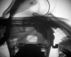
X-ray movie system captures airbag ignition
From ignition of an automotive safety airbag to full deployment takes just 150 ms. The visible part of the process has been well documented; however, the first 10 to 20 ms during which the airbag is ignited and begins to unfold are essentially hidden from view with only isolated photos of this critical phase.
Philip Helberg and his colleagues at the Ernst Mach Institute of the Fraunhofer Institute for High-Speed Dynamics (Efringen-Kirchen, Germany; www.emi.fraunhofer.de) have developed a procedure that makes it possible to render the entire process visible. Using an extension of flash x-ray technology, he creates image sequences with intervals of no less than 10 μs at up to 100,000 frames per second. Exposure time per image is 20 ns so motion blurring is insignificant.
“A resolution of 1000 images per second is sufficient for examining the airbag ignition process,” says Helberg. The sequence begins about 5 ms after the airbag is activated, and finishes 8 images and 8 ms later. Multiple x-ray flashes irradiate the object under examination from one direction. The unabsorbed radiation strikes a fluorescent screen on the opposite side and illuminates it for 1.6 μs. The images are registered by a CCD camera or an array of cameras positioned behind the screen. With the help of these exposures, airbag manufacturers should be able to determine the best way to stow airbags in their housings so that they unfold in the optimum manner.
