Vision system finds panel display defects
By Andrew Wilson, Editor
PC-based cameras, frame grabbers, and lighting devices combined with special software and motion control automate the defect analysis of flat-panel displays
Lightweight and rugged, flat-panel displays (FPDs) are proliferating in a variety of industrial and consumer products, including digital cameras, video games, high-definition TVs, cellular phones, and personal digital assistants. To inspect these FPDs, Sokkia Corp. (Tokyo, Japan) has manufactured the PIS-1500SR II system based on its experience in inspecting printed-circuit boards (PCBs), liquid-crystal displays (LCDs), and plasma display panels (PDPs).
For example, as each PDP exits a manufacturer's production line, the Sokkia PIS-1500SR II system inspects it for defects that are invisible to the naked eye and often escape human inspection. These defects only become apparent over time, when different pixels are powered during regular use of the display. Since some FDPs are large and heavy, returning a defective panel is extremely inconvenient for the consumer and costly to the manufacturer. Adaptable to robot handling and conveyor-to-conveyor transfer, the PIS-1500SR II system can inspect FDPs up to 42 in. wide, with a maximum inspection area of 1550 ¥ 1100 mm.
While evaluating the best machine-vision components for its system, Sokkia faced several engineering challenges, including the quantity of inspection data that needs to be captured and processed. Indeed, the sheer quantity of data that the system needs to acquire about each PDP to perform accurate inspection and the need for rapid throughput to keep pace with high-speed production required a fast image-acquisition and processing subsystem.
Based on these requirements, Sokkia needed a system that would offload the majority of image-acquisition and processing tasks from the host CPU, freeing it to perform system control functions. In addition, interfacing to a Japanese graphical user interface (GUI) was a major requirement. Although the company wanted to locate the best inspection component provider for the job, system development necessitated a Japanese-speaking supplier. Based on these requirements, Sokkia chose Coreco Imaging (St. Laurent, QC, Canada) to provide the PC-based image-acquisition and processing technology for the application.
High-speed imaging
Yvon Bouchard, applications manager for Coreco Imaging's Quebec-based applications group, says, "After manufacturing, various kinds of defects can appear on an FPD. These include serious facets such as cracks in the glass, which cause open connections in the TFT of the FPD and shorts where the metallization bridges two wires." Other less serious defects consist of bites where parts of the square conductor are not metallized correctly or protrusions where more metallization has occurred than needed. "Dust, debris, and other deposits can also be deposited on the glass during fabrication and must be inspected," says Bouchard.

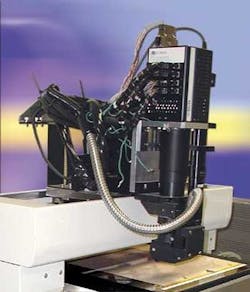
To perform the inspection of FPDs automatically, defects as small as 5 µm must be identified. At this precision, defect detection is performed by first loading the FPD onto an inspection station that consists of a flatbed table and an overhead x-y-z gantry. To illuminate and image the flat panel, an imaging system consisting of a metal-halide illuminator with a gooseneck light guide and a linescan camera, are mounted on the x-y-z stage. Under control of the host PC, the x-y stage is moved over the flat panel in a serpentine direction (see Fig. 1).
Images are then captured using a CT-F6-2K monochrome digital linescan camera from Dalsa (Waterloo, ON, Canada). This camera uses a time-delay-integration (TDI) method to increase the responsivity of the camera compared with conventional linescan cameras and permit greater scanning speeds in low light or allow reduced lighting levels at conventional speeds. "The camera runs at up to 80-kHz line rates, so a standard linescan CCD camera cannot be used since there is not enough light to properly image the display," says Bouchard.
"To inspect different types and resolutions of defects, Sokkia engineers designed the system so that the inspection resolution can be adjusted to 5, 7.5, or 10 µm by the user. This adjustment provides up to 150,000 lines of image data per inspection pass. Each pass covers about a 2- to 4-cm width, depending on the resolution. Therefore, an 1100-mm panel needs 27 to 55 passes, and a resultant image data per inspection of 2048 X 150,000 X 55 equals 16.896 Gbits," says Bouchard.
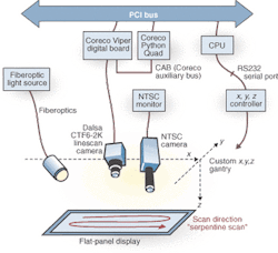
Eight-bit data in RS-422 differential format from the TDI camera are captured by a Coreco Imaging Viper-Digital frame grabber in the host PC. This frame grabber is a single-slot video-acquisition and preprocessing board for the PCI bus that scans strips of 2 to 4 Kbytes across the image and reconstructs images in on-board memory. After the images are digitized, the uneven illumination across the pixel field generated by the camera and illuminator is automatically corrected by applying a flat-line or flat-field correction process (see Fig. 2).
Image analysis
"After flat-line correction is performed on the Viper-Digital board," says Bouchard, "the board's optional pixel processor performs adaptive thresholding on the gray-scale image." This process separates foreground image objects from their background based on the difference in pixel intensities of each region. "While global thresholding uses a fixed threshold for all pixels and works only if the intensity histogram of the image contains neatly separated peaks, local adaptive thresholding selects an individual threshold for each pixel based on intensity values in its local neighborhood. This allows thresholding an image whose global intensity histogram does not contain distinctive peaks," he adds.

Adaptive thresholding results in a binary image that can highlight multiple FPD defects. After images are binarized in this fashion, the image containing defect information is transferred via the Coreco auxiliary bus at up to 200 Mbytes/s to a multiple TI6201-based Coreco Viper Quad board. Also PC-based, this board supports as many as four DSPs interconnected via high-speed links and communicates image data quickly among processors.
Faced with processing up to 16 Gbytes of data per panel, defect detection had to be performed in real time. In the PIS-1500SR II system, up to four TI6201 DSP processors perform different functions to resolve various features of the panel under test. During operation, individual images containing binary defect data are loaded into the main memory of the Viper Quad board. Here, proprietary Sokkia-developed algorithms run separately on each processor to determine defect types, including opens, shorts, bites, and protrusions, among others.
After individual defects are classified, the types of defects and their locations are passed to the host PC. Here, the host creates a graphical defect map that represents the area of the FPD with all of the defects color-classified. "Although thousands of defects can be identified by the system," says Bouchard, "only a certain number will be significant enough to reject a panel."
To ensure that such rejects are significant, the x-y-z positioning stage also features an NTSC-based color camera manufactured by Toshiba America (Irvine, CA) and illuminated by a second halogen light source by Thales Optem (Rochester, NY), whose output is coupled directly to an NTSC monitor. At the end of each inspection, detected defects are reported to the user for review with this off-line color camera. "After selecting the defect from the GUI, the stage is moved automatically to the defect position where it can be imaged by the NTSC camera," says Bouchard. "Because the lens on the camera has a high magnification, images as small as 1um are represented across a 1-cm distance," he says. "This allows the user to manually determine whether the defect is critical to the operation of the display."
Graphical interfaces
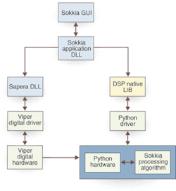
In the software design for the PIS-1500SR II system, Coreco and Sokkia codeveloped a GUI to decouple Coreco's Sapera Windows-based software library for image acquisition, processing, and analysis, as well as the DSP native library for the Python board with Sokkia's application dynamic link library (DLL; see Fig. 3). "To accomplish this," says Bouchard, "the Sokkia application DLL performs all the low-level functions, such as initializing system buffers, setting the frame size, and loading Sokkia's proprietary image-processing code into hardware," says Bouchard. "In this way, Sokkia application engineers did not require an understanding of the low-level functions of either the Viper or Python boards. Instead, they were presented with a high-level GUI that could be used to load image-processing code for both processor boards."
According to Naoyuki Kani, president of Japan F.A. Systems Corp. (Yokohama, Japan), Coreco Imaging Japanese representative, the biggest challenge for engineers was tackling both inspection accuracy and speed. The resulting Sokkia inspection system accelerates data throughput and reduces production bottlenecks, enabling complete inspection of a 42-in. PDP and its end connector in approximately 46 s. "By shifting the burden of image processing to an embedded DSP on the Python/C6 multi-DSP processor board, the host computer can control the x-y-z gantry motion and the user-interface functions," says Kani. ..
Coming in November Spotlight on Manufacturing Automation