Vision system checks asthma inhalers
Integrated vision/test system measures plastic injection-molded asthma inhalers to ensure product quality.
By Randy Salley
Many asthma sufferers use hand-held spray inhalers to administer medication to their lungs. Whereas metered-dose inhalers and dry-powder inhalers use different delivery mechanisms, they essentially transfer prescribed medicine either by propellant or direct inhalation. In both cases, the manufacturing tolerances of the inhalers' opening are critical in delivering the correct dose to the patient.

To manufacture the large number of inhalers required in today's market, injection-molding machines are used, in which heated plastic is forced into steel or aluminum molds under high pressure. After the mold cavity is filled, the plastic cools and solidifies into a finished part. This process cost-effectively controls the manufacture of millions or billions of pieces over short time periods.
Bespak (Apex, NC), a designer, developer, and manufacturer of drug-delivery devices, with operations in England and the United States, uses this process to manufacture more than 31,000 injection-molded asthma inhalers a day. Immediately after molding, the critical dimensions of the asthma inhalers are measured to support the company's quality-control and just-in-time manufacturing philosophy.
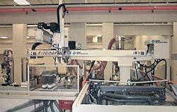
Under contract from Aventis Pharmaceuticals (Bridgewater, NJ), Bespak engineers designed and integrated a vision-inspection system that checks every plastic inhaler immediately after the molding process (see Fig. 1). Those inhalers that do not meet critical tolerances for both diameter and oval shape of the inhaler's spray opening are rejected. Defective inhalers are flagged as rejects and dropped into a reject bin. Acceptable inhalers are transported by separation tubes to collection bins.
System designIn the vision-inspection system design, a T-FM1000 three-axis servo-controlled robot from Star Automation (Boeblingen, Germany) loads and unloads inhalers onto a vision-inspection platform. In a fully automated operation, the molding press ejects inhaler parts into the robot's end-of-arm (EOA) tooling. This tooling comprises eight individual grippers that are machined to fit the contour shape of the top portion of the inhalers.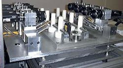
Two sensing positions for each gripper detect the presence or absence of the inhalers at different intervals during the molding and testing cycle. After the robot accumulates eight inhaler parts in a gripper, the inhalers are placed onto the test-fixture platform of the vision-inspection system. Floating on spring-loaded ball transfers, the test-fixture platform allows free x-axis, y-axis, and rotational movements. Consequently, operators can quickly align the test fixtures to the EOA tooling and the inhaler spray heads. After the vision-inspection system is in proper position, the operator tightens two knurled rim-clamping knobs to secure the test fixture.
To build a fully automated system, Bespak engineers designed a complete test system that integrates the vision-inspection station, the servo robot, and the molding press. If any one of the three sections fails, the other two sections are notified via a communications link so they can respond immediately.
When the robot acquires the newly molded inhalers, it verifies that all the parts are present. If the robot detects a missing part, it alerts the integrated test system. Then, the inspection station and the molding press react instantly to stop the molding press from closing on an inhaler and damaging the EOA tooling.
If the test station becomes misaligned with the EOA tooling as the inhalers are being placed onto the test fixtures, the vision-inspection station immediately stops the robot's downward motion to prevent destruction of tooling or parts. Numerous system operational checks are made to verify and protect equipment and their movements.
After the inhalers are placed in the test fixtures by the robot, they are inspected by the vision-inspection system, which incorporates off-the-shelf cameras, image processors, and lighting devices (see Fig. 2). To inspect eight inhalers at a time, the vision system captures eight separate images. Imaging is accomplished by mounting eight XC-75 CCD cameras from Sony Electronics (Park Ridge, NJ) onto the test-fixture platform. By using a 50-mm fixed-focal-length lens, each of the eight cameras captures a separate view of the opening of each of the eight inhalers.
To digitize these images, the outputs of the eight cameras are multiplexed by a CheckPoint 900 PCI bus-based image-processor board from Cognex Corp. (Natick, MA). Housed in a Pentium III-based PC, the board supports up to four gray-scale cameras with simultaneous acquisition. In this setup, the multiplexer board switches the image data from one group of four cameras to the second group of eight cameras. In addition to serving as host to the vision system, the PC also remotely controls the proper illumination of two Schott-Fostec (Auburn, NY) fiberoptic light sources through an RS-232 communications link.
Vision designOnce the robot has placed the inhaler parts on the test-fixture platform, a SLC 505 programmable logic controller (PLC) from Rockwell Automation Allen Bradley (Milwaukee, WI) triggers the acquisition of the first group of four images. After the four images are acquired, the vision system triggers the multiplexer to acquire the next set of four images from the second group of four cameras. It then verifies that the camera connections have been changed, and the second set of four images has been acquired.After the acquisition of all eight images, a postacquisition signal from the last camera resets the camera multiplexer to its original starting status to begin the next acquisition cycle. While the acquiring, signaling, and switching functions are taking place, the vision system processes and tests the images for inhaler dimensions and sends the appropriate pass/fail signals to the next step of system operation. Acquisition and processing of all eight images occur in just over one second.
After an image is acquired, the test system locates the opening of the inhaler, determines its center and shape, and verifies the measurement tolerances. To accomplish these checks, engineers at Bespak used the Search tool in the Cognex CheckPoint program supplied with the CheckPoint board. Once the inhaler is located, a blob tool determines the center of the inhaler's opening and its major axis of rotation. These data are important because the determination of the opening's oval shape is used to fit an ellipse configuration to the opening based on the major axis.
The diameter of the opening is checked using CheckPoint's Edge and Arc Gauge tools. These tools are programmed to acquire 72 radial points. The vision system then uses these acquired points to calculate an average diameter. It also uses the radial points to analyze the opening configuration to determine if its shape is within a specific oval tolerance set (ratio of longest to shortest diameters). This entire inspection cycle time including capture and calculation takes approximately 200 ms with the bulk of the time dedicated to image capture.
Human-machine interfaceTo customize a visual operator interface for the CheckPoint vision application and PLC control, the Bespak engineering team created a human-machine interface using National Instruments (NI; Austin, TX) LabVIEW, a Windows-based development software package. During operation, the CheckPoint vision software exchanges data and command strings with the LabVIEW application using the CP Communication tool, Checkpoint's ActiveX custom control (see Fig. 3).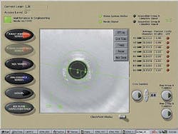
LabVIEW also communicates with the PLC using the PC's Ethernet communication protocol and LabVIEW's data-logging and supervisory control module. Various screens display vision data, PLC counters, and other valuable tags acquired from the PLC. This visual interface feature makes CheckPoint and the vision system easy for operators and maintenance personnel to operate, test, and calibrate the test system without having to access the complicated features of the full development system.
Lighting controlA key problem of making vision measurements is the elimination of lighting variations. To do this, both the vision system and the host computer monitor the intensity of the halogen light source. This is necessary because, as the quality and the intensity of the halogen bulb degrade over time, the image quality would deteriorate. Without consistent lighting, the vision system cannot detect the well-defined edges of the inhaler opening, which affects the reliability and the repeatability of the test results.To automatically analyze and adjust the light-source intensity, the CheckPoint system uses the CheckPoint Light Meter tool to assign a "light value" for the total image each time an image is acquired. This value transfers to LabVIEW through CPComm to evaluate the light intensity. In this operation, LabVIEW communicates with the light source through the serial RS-232 communications port of the host PC. If the intensity value is out of range, the host PC sends a hexadecimal value to the light source that adjusts its intensity into range, and the new intensity is verified on the next machine cycle.
Because the lighting feedback loop works within a narrow intensity range, the vision system never sees a difference in image quality. This entire subroutine is possible because of CheckPoint's Light Meter and CPComm features. Even as the light dims with age, the lighting-control system automatically increases its power to restore its original intensity, guaranteeing consistent results.
Future inspection developments include the evaluation of a vision system that uses a high-speed video camera to capture the spray pattern of each inhaler. The spray pattern vision inspections will be done next to the molding press, and the spray patterns will be measured against US Food and Drug Administration regulations to ensure inhaler quality and reliability.
RANDY SALLEY is plant manager at Bespak, Apex, NC 27502.
Company InformationAventis PharmaceuticalsBridgewater, NJ 08807www.aventispharma-us.comBespakApex, NC 27502www.bespak.comCognex Corp.Natick, MA 01760www.cognex.comNational InstrumentsAustin, TX 78759www.ni.comRockwell Automation (Allen-Bradley)Milwaukee, WI 53204www.ab.comSchott-FostecAuburn, NY 13021www.schott-fostec.comSony ElectronicsPark Ridge, NJ 07656www.sony.comStar AutomationD-71032 Boeblingen, Germanywww.star-automation.com