Microscopy tests fiberoptic parts
Microscope-based optical coordinate system enables precision user-programmable, noncontact, dimensional measurements of fiberoptic components.
By Andrew Wilson, Editor
To automate the inspection of fiberoptic components, systems integrators are developing microscope-based systems that meet challenging dimensional requirements. While such systems use off-the-shelf microscopy products to capture image data, they also use novel lighting methods, image-processing software, and networked computer systems. Such systems are targeted at measuring multifiber terminators, ferrules, and v-grooves developed by such companies as CoorsTek (Golden, CO, USA), 3M (St. Paul, MN, USA), and Schott Glas (Mainz, Germany).
A producer of noncontact measuring instruments, Micro-Metric Inc. (MMI; San Jose, CA, USA) develops automated and manual measuring microscopes for dimensional measurements. According to Tom Pelton, founder and chief executive officer, applications for these systems range from industrial inspection to scientific and research investigations.
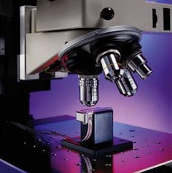
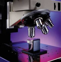
The company's FiberLine optical coordinate-measuring system is based on its Integrated Measuring System (IMS) series of automatic coordinate-measuring microscopes (see Fig. 1). Designed for applications requiring accurate noncontact dimensional measurements, IMS systems are typically used when measurement accuracy requirements are between 0.01 and 1 µm.
To attain this accuracy, the IMS includes a custom-built x-y stage and a dc servomotor positioning system that provides x-y-z positioning with little vibration. With its vision system and MCL programming language, FiberLine performs user-programmable sequences of automatic optical coordinate measurements that include outside diameter (OD), core diameter, core-to-OD concentricity, fiber roundness, and spatial distribution of emitted light from fiberoptic terminators and ferrules.
FiberLine also provides a measure of the concentricity between the outside diameter of the fiber and its core and an intensity profile of emitted light. Measurement data can be analyzed according to user-defined instructions to provide screen display, reporting, printouts, disk storage, and networked transmission of results. Output can be produced in a text format for use with standard spreadsheets and statistical process control programs.
Adding vision
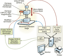
In the design of its system, MMI used a number of off-the-shelf components, including microscopes, cameras, frame grabbers, motion controllers, and illumination devices (see Fig. 2). To achieve the high measurement accuracy required to measure fiberoptic components such as ferrules and multifiber terminators, the system incorporates a high-magnification objective lens in conjunction with a BX Series microscope from Olympus America (Melville, NY, USA).
According to Pelton, this microscope was chosen because it could be easily integrated as an OEM component to the measurement machine. "In our other semiconductor-inspection products," he adds, "the microscope's motorized nose piece (a revolving turret mounted with multiple lenses) allows objective lenses to be automatically changed for multiple inspections at different resolutions."
To digitize the images from the microscope, MMI chose the UP-600 camera from Uniq Vision (Santa Clara, CA, USA). With 659 × 494-pixel, full-frame resolution, this digital camera uses a progressive-scanning interline-transfer CCD. "In addition to featuring 60-frame/s output," says Pelton, "the camera's square pixels are especially suitable for processing, measuring, and analyzing tasks."
Because the resolution obtained by the camera depends on the magnification of the microscope, the system can obtain pixel resolutions below the optical resolution of the microscope. "Thus," Pelton says, "the 659 × 494 format of the imager presents no problems in obtaining 0.1-µm pixel resolution."
The UP-600 camera is compatible with popular frame grabbers, including the PC-DIG from Coreco Imaging (St. Laurent, QC, Canada) used by MMI. Because the FiberLine optical measurement system uses both PCI and ISA boards, MMI chose to house the frame grabber in a passive back plane from I-BUS (San Jose, CA, USA), which supports both PCI and ISA bus form-factors.
As a PCI-compatible board, the PC-DIG interfaces to the Uniq-600 digital camera through the PC-DIG's 32-bit differential interface. After images are digitized, the board transfers video data to a host PCI-based memory controller using bus mastering at sustained transfer speeds of up to 120 Mbytes/s.
According to Pelton, the PC-DIG board was chosen as the frame grabber in the system because MMI had used Coreco's older PFG-Plus board in its designs and was familiar with the Itex programming library. "This library was used in other products to perform pattern-recognition functions such as automatic detection of fiducials on semiconductor wafers," he says.
Most important, however, images captured at 60 frames/s by the camera had to be displayed on screen using Microsoft's Direct X protocol. "The combination of a relatively small-pixel-count camera, a high-resolution optical system, and PCI data transfer," says Pelton, "allows us to get image data into PC memory at the same time as a PCI-based VGA card is displaying captured images at frame rates."
Motion control
To perform the high-precision x-y-z control of the motorized stage, a MCX-DSP 8- to 16-axis ISA-bus, motion-control, data-acquisition board from Precision Micro Dynamics Inc. (PMDI; Victoria, BC, Canada) was integrated into the I-BUS passive back plane. Running under Windows software, the board includes an ADSP-21061 SHARC DSP from Analog Devices (Norwood, MA, USA), SRAM memory, timers, 128 digital I/O lines, eight ADCs and 16 DACs.
"On this board," says Pelton, "several gate arrays provide combinations of quadrature decoder inputs and analog motor outputs." Using PMDI MCI-SoftLIB-WIN register-access libraries and motion-control libraries, MMI engineers developed routines that allow high-level programming of synchronous multiaxis moves, asynchronous multiaxis moves, linear interpolation, and circular interpolation. For motion-control development, PMDI's MotionTools graphical-user interface (GUI) was used to view data using an oscilloscope utility and to manipulate motion parameters.
"In addition to controlling the motion of the x-y-z stages," says Pelton, "the MCX-DSP board both controls the lighting intensity of the image under the microscope and drives the lighting to the fiberoptic components under test. To illuminate the image, the system uses a Fostec DCR-II microscope image illuminator from Schott Fiber Optics (Southbridge, MA, USA) mounted above the objective lens of the microscope.
To make accurate measurements of fiberoptic terminators and ferules, the system also drives light into these fibers using another DCR-II illuminator as a fiberoptic illuminator. "Under control of the MCX-DSP board, the amount of lighting entering the fiber can then be adjusted as required," says Pelton.
To attain the precision required in the FiberLine system, the company uses its proprietary x-y stage manufactured from cast iron with hardened-steel guide ways. "The individual needle bearings for vertical and horizontal guiding used in the design," says Pelton, "result in a straightness of less than 0.05 µm/100 mm and an angular straightness of 2 arc sec or less with a bidirectional repeatability of 0.2 arc sec. Mounted on an adapter plate fixed to a granite z-column, MMI's custom Micro-Focus Block provides extremely precise z-motion while allowing the optical focus point to be positioned at any height from 0 to 4 in. above the stage surface.
"Because of the weight of the x-y-z stages," says Pelton, "it is important to use an x-y servo motor controller that can delicately move the mass to attain the accurate measurements required." To accomplish this movement, the FiberLine design incorporates a dual-loop servo that combines feedback from rotary encoders on the motor shafts with two noncontact linear encoders from Heidenhain (Schaumburg, IL, USA) with 10-nm (0.4-µm) resolution.
A rotary encoder mounted on the motor drive provides high-frequency feedback of the position and velocity of the motor shaft, and a second encoder mounted on the x-y stage provides linear positional information. After the signal is filtered from the x-y stage encoder, it is combined with high-frequency data from the motor encoder and fed to the MCX-DSP board. This dual-loop servo control provides the system with high-speed positioning at high accuracy and repeatability.
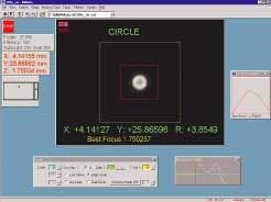
During the design of the man-machine interface, MMI chose to develop its own GUI using Microsoft C++. By using Visual C++ running under Windows, the MMWIN GUI can be used to display images in real-time, set up measurement parameters, control the motion of the x-y-z stage, and store measured information in a database format on the system (see Fig. 3). "By developing MMWIN using Visual C++," says Pelton, "we have a GUI that can access and use the high-level imaging, DSP, and motion-control libraries from Coreco Imaging and PMDI at very high speeds."
Making measurements
Concentricity, the measurement of how well the fiber is centered within the ferrule, is an important measurement parameter of fiberoptic components. To compute this parameter, the coordinates of the outside circle of the ferrule and the coordinates of the inner circle of the fiber core must be measured. If these coordinates are the same, then the concentricity of the fiber is zero and the fiber is perfectly centered within the ferrule.
Using the FiberLine system, the operator is first presented with a screen that shows the area under test. The system uses an autofocus method that captures multiple images of the fiber under test at different focus points to properly focus the image. Performing a gradient detection between adjacent pixels in each of these images and computing the highest average gradient between different pixels enables the calculation of the best focus position. After focusing, the system can automatically perform concentricity, diameter, and roundness measurements at 0.015-µm accuracy and then output the data in Excel (see table on p. 33).
"In the past," says Pelton, "such measurements were performed manually by operators using toolmaker's microscopes or profile projectors. These methods were time-consuming and laborious and subject to operator inaccuracy and fatigue." Now, accuracy, repeatability, and throughput have been increased dramatically.
Parameters such as fiber-core measurement, for example, can be achieved in about 3 s using the $140,000 system. Multifiber terminators, which can accommodate as many as 96 rows of fibers in multiple configurations such as 16 × 6, can be analyzed in less than 30 s. "Although the FiberLine system is not optimized for high-production environments where thousands of parts need to be measured, versions of the system could be tailored to meet such demands," says Pelton.
Fiberoptic assembly and test market to increase
According to last year's Automated Assembly and Test of Fiber Optic Components, published by ElectroniCast (San Mateo, CA, USA), the global consumption of fiberoptic-component-assembly equipment and related test units was projected to increase from $722 million in 2000 to $1.71 billion in 2005. In 2000, however, a substantial share of this value consisted of technology-augmented manual-assembly stations. Indeed, manual-assembly products in 2000 held a 20% share of equipment value.
Over the 2000–2005 span, the fully automated equipment value share is expected to expand from 2% to 7%, and the semi-automated share to expand from 69% to 74%. These automated assembly systems reduce cost per unit and increase profitability by increasing yield and providing a faster, more-efficient ramp-up to high volumes.
"The challenge of converting from manual to semi- or fully-automated assembly of fiberoptics is to achieve a high enough production volume to amortize the assembly-line cost at a low cost per unit," says ElectroniCast chairman and founder Jeff D. Montgomery. "The near-term challenge for automated assembly vendors," he says, "is to develop product-specific automated assembly lines that can be amortized with relatively low-priced components."
A. W.
Company Info
Analog Devices www.analog.com
CoorsTek www.coorstek.com
Coreco Imaging www.imaging.com
ElectroniCast www.electronicast.com
Heidenhain www.heidenhain.com
I-Bus www.ibus.com
Micro-Metric Inc. (MMI) www.micro-metric.com
Olympus America www.olympusamerica.com
Precision MicroDynamics Inc. www.pmdi.com
Schott Fiber Optics www.us.schott.com
Schott Glas www.schott.com
3M www.3m.com
Uniq Vision www.uniqvision.com


