Machine-vision system inspects fiber connectors
Off-the-shelf microscopes, frame grabbers, and software team up to automate fiber inspection.
By Andrew Wilson, Editor
In Internet system designs, routers connect networks and route information packets. While routers in access networks let businesses connect to Internet service providers (ISPs), in enterprise networks routers link tens of thousands of computers. Similarly, to link ISPs and enterprise networks with long-distance carriers, network backbone routers switch a few links at high speed.
To meet the demands of today's businesses, developers of enterprise routers are building systems with many high-speed low-cost ports. To do this, router developers offer systems that use multiple crosspoint switches to route data.
To interface these systems with other switches and routers in the system, data from the router can be transferred optically between systems. Here, transmit and receive optics are used to convert data so that the information can be transmitted across a fiberoptic interface. Parallel optical devices (PODs) that reside on the router perform this function. Often multiple PODs are linked with MTP connectors to backplane edge connectors such as high-density backplane MT (HBMT) connectors that can terminate multiple MTP connectors from the PODs.
Using a standard 12-fiber MT ferrule as the optical interface, a single HBMT connector can provide up to 48 fiber interconnects. As such, it is often used for connecting backplanes and crossconnect systems in computing equipment and telecommunication equipment including transmitters, switches, multiplexers, and demultiplexers. While HBMT connectors can terminate multiple MTP connectors and provide a high-speed edge connector for router boards, the number of fibers that are then terminated often becomes very large.
Multiple terminations
In their latest generation of routers, for example, developers use a number of cards, backplanes, and cables that incorporate a variety of high-density connectors. For example, one single card could have many rows of multiple card edge connectors, each capable of terminating a number of MTP connectors that each carry many optical fibers arranged in a linear pattern. With redundancy built in, this results in hundreds of fibers that are terminated at the edge connector. Each one of these fibers must be optically tested for scratches, cracks, chips, voids, and fixed contaminants at numerous points in the manufacturing and assembly process.
"These defects can increase both the backreflection and insertion loss of the fiber interface, as well as prevent proper mating of the connector," says Douglas Wilson, president of PVI Systems (East Lyme, CT, USA). If the fiber has multiple scratches, for example, light reflected from the cleaved end of a fiber will increase and power throughput will decrease. As data bandwidths increase, minimizing the connectors losses associated with these defects becomes more critical to overall optical system performance.
To inspect these defects, fiberoptic-connector vendors typically have used microscope-based systems and manual defect-detection methods. As well as being time-consuming, this process is labor-intensive and subject to human error. Furthermore, little or no data to support process control improvements are collected. For router and other high-density fiberoptic components, the need to inspect the same fiber at multiple points in the supply chain with consistent results is virtually impossible using manual inspection techniques.
Automated visual inspection
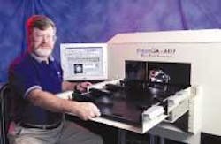
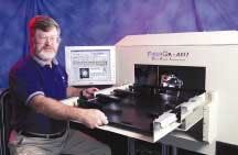
To semi-automate the process of fiber inspection, PVI Systems developed the Fiber QA-EFI, a PC-based system that uses microscopes, frame grabbers, and standard PCI-based host computers (see Vision Systems Design, July 2002, p. 24). Now, due to interest from router and connector vendors, PVI has developed a fully automated system that can inspect products with up to several hundred fibers each. The new system, FiberQA-AVIT, builds on the FiberQA inspection engine, adding motion control and automated focusing to totally eliminate operator interaction, except for loading and unloading of parts to be tested (see Fig. 1). The AVIT system can inspect fibers anywhere in its 600 × 235-mm opening with a standoff distance of more than 30 mm and a range of depth of more than ±20 mm.
Says Wilson, "The FiberQA-AVIT system must also inspect a number of fibers in other connectors including SC and FC versions." The company is developing a combined motion/vision system that uses multiple fixtures to accommodate a number of different board sizes with a number of different edge connectors. Dynamic Test Solutions (Pawtucket, RI, USA) was selected by PVI to design and fabricate the AVIT enclosure and initial set of test fixtures. To do so, multiple MTP connectors in the HBMTs and similar array connectors must be located, the alignment pins located and each individual fiber termination inspected.
Connector location
In the manufacture of the automated fiber-inspection system, PVI uses a number of off-the-shelf components including lenses, x-y-z stages, cameras, frame grabbers, and motion controllers. These components, along with their PC controllers, are mounted in a custom enclosure and fixture receiver.
The various parts to be inspected have their fibers located in three dimensions. The exact location of each fiber cannot be determined a priori, due to manufacturing and fixture tolerances. The system must first determine the location of the each ferrule in the field of view (FOV). The system can then precisely align the optics to locate the first fiber in the topmost left MT ferrule in the high-density backplane connector.
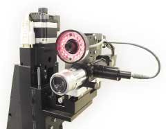
To roughly locate the position of the connector, the system uses a PCI-based host PC populated by off-the-shelf frame grabbers and motion controllers. The FiberQA-AVIT system employs a dual camera system, mounted on an x-y-z positioning stage from Danaher Precision (Washington, DC, USA), to maximize throughput (see Fig. 2). The first camera, an STC-400 RS-170 CCD camera from Sensor Technologies America (Sentech; Carrollton, TX, USA) with an InfinStix lens from Infinity Photo-Optical Company (Boulder, CO, USA), images a FOV larger than the ferrule. This camera determines the precise location of the ferrule and the individual fibers accurately enough for the high magnification system to image individual fibers. Additionally, the image from this camera is presented to the operator for visual inspection of the condition of the ferrule.
Using the camera, images are then digitized into host PC memory by one channel of an IMAQ-1409 frame grabber from National Instruments (NI; Austin, TX, USA). "Because the camera only needs to determine the approximate location of the connector," says Wilson, "we could use a low-cost interlaced camera such as the STC-720." Once images are located in host memory, an edge-detection algorithm finds the edges of the connector and the centers of the alignment holes or pins. From this information, the location of each fiber in the MTP connector can be determined to about ±15 µm.
Finding fiber
After the location of the fiber in the MTP connector is found, the fibers at the end of the connector must be imaged in a 250-µm FOV. To accomplish this, a Sentech STC-1100 progressive-scan camera fitted with a 10x objective lens from Mitutoyo America (Aurora, IL, USA) and Precise Eye lens assembly from Navitar (Rochester, NY, USA) is located next to the STC-720 camera.
"Because the displacement of the cameras is known, the motion-control system can accurately move the progressive-scan camera to the exact location of the first fiber on each MTP connector," says Wilson. To alleviate the problems with interlacing, the STC-1100 progressive-scan mode allows 640 × 480 images to be captured using another channel of the PCI-based IMAQ-1409 frame grabber.
Before images can be captured by the high-resolution camera system, however, the x-y-z stage must be moved into position. To do this, PVI Systems chose the National Instruments PCI-7334 stepper motor controller. In turn, this drives the MDrive stepper motors from Intelligent Motion Systems (Marlborough, CT, USA), with integrated drivers, on the x-y-z stage.
Once the fiber's location is known, the system moves the high-resolution camera to each fiber's location in turn. To capture a high-quality image, the system uses the z-axis stage to position the camera at the optimum focus location. This is done in an efficient manner by taking advantage of the triggering and synchronization capability of the NI motion controller and frame grabbers. The z-axis stage is commanded to move a fixed distance. Simultaneously, the frame grabber acquires images and sends a trigger signal to the motion controller card. Using a progressive-scan camera allows the AVIT system to capture images while moving without introducing interlace motion blur. The motion-controller card buffers the encoder position values for each received trigger. Thus, each image is tagged with its exact location in the z direction. To accurately determine the focus and position of the fiber in the MTP connector, the system uses a number of proprietary algorithms developed by PVI. The focus is computed by the time the focus move is completed. After focusing of the single fiber is achieved, an image of the face of the fiber is taken and stored on the system's hard drive.
Motion and vision
To move the x-y-z stage and analyze captured images for scratches, cracks, and chips, PVI Systems uses NI IMAQ Vision Builder, IMAQ Vision, NI Motion, and LabVIEW software. Vision Builder, a scripting environment for IMAQ Vision that requires no programming, was used to prototype gauging, alignment, inspection, and counting applications and generate LabVIEW code, called a Virtual Instrument (VI), using IMAQ Vision for LabVIEW. "Integrating this software with NI motion VIs," says Wilson, "allows vision-based motion control systems to be developed rapidly."
To rapidly process the images of the fiber, single 300-kbyte images are passed from the main host CPU in a lossless PNG image format to a second 3-GHz PCI-based Pentium host over 10/100BaseT Ethernet. The PC runs PVI Systems FiberQA software to determine numerous end-face fiber parameters such as scratches and chips, including their exact locations on the end face.
In the specification for the system, both router and connector manufacturers required that one fiber be inspected every 4 s. Thus, several hundred fiber terminations can be located and inspected in approximately one hour.
"Testing such boards manually using a microscope-based technique required at least 12 hours of manual labor," says Wilson. Even after manually testing, such inspections provided only pass/fail data—no quantitative data of scratches, cracks, and chips on the fiber was stored. Now, using the automated fiber-test system, complete boards with several hundred fiber terminations can be fixtured and tested and the results stored in a database in less than one hour.
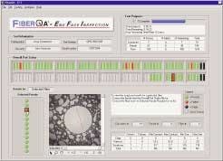
Developing the graphical user interface (GUI) was also accomplished using LabVIEW. Similar to the interface used in the company's previous fiber-inspection system, the GUI uses a number of bars, buttons, images, and data-display windows (see Fig. 3). In determining the overall part status of the system, the GUI displays the end faces of the MTP connectors as a number of bars. A database of fiber tests is also presented in the display.
PVI systems has leveraged the software expertise of its initial FiberQA system into a system that combines motion and vision to test multiple fibers in router backplane connectors. According to Wilson, his company is under contract to develop automated vision inspections with a number of automotive and pharmaceutical vendors for nonfiber applications.
Company Info
Danaher Precision www.danaher.com
Dynamic Test Solutions www.dynamictest.net
Infinity Photo-Optical Company www.infinty-usa.com
Mitutoyo America www.mitutoyo.com
National Instruments www.ni.com
Navitar www.navitar.com
PVI Systems www.pvisys.com
Sensor Technologies America (Sentech) www.sentechamerica.com


