Machine-Imaging system manages harvester

SPOTLIGHT ON MACHINE VISION
Automatic harvester integrates cameras, frame grabbers, CPUs, and software with directional systems to mow field crops.
By Andrew Wilson,Editor
Today, agricultural harvesting machines are operated manually. In practice, the worker soon tires of this monotonous task and makes errors. An automatic harvester, however, would solve many labor, time, and expense problems. Not only would such an automated system be more accurate than those run by human operators, but they also could be continuously operated in robotic mode for 24 hours a day/seven days a week, if necessary.
Because the harvester speed is slow, crop obstacles are uncommon, the farm-field environment is highly structured, and the cutting and movement tasks are repetitive, automating the operation of a harvester machine using vision and imaging techniques appears straightforward. In the design of such a harvester, though, a collaborative effort found the need to integrate a host of support components.
Team effort
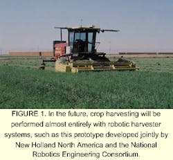
Teamed with New Holland North America (New Holland, PA), the National Robotics Engineering Consortium (NREC; Pittsburgh, PA), a commercial organization of the Robotics Institute at Carnegie Mellon University (Pittsburgh, PA) where commercial robotic and operator-assist systems are being evolved from research prototypes developed at NASA and other research laboratories, is developing such an automated harvester. Slated to be deployed soon on New Holland's product line, the Demeter harvester system uses off-the-shelf cameras, frame grabbers, computers, and software in conjunction with several directional systems to harvest field-crop acreage to an accuracy of ±3 cm (see Fig. 1).
Developed by commercialization specialist/senior software engineer Tom Pilarski and his colleagues at the NREC, the prototype system is currently deployed on a New Holland 2550 Speedrower harvester machine. The harvesting system uses two navigation subsystems based on visual data and global-positioning-system (GPS) data to provide precise guidance and automation.
"Each navigation system offers unique advantages," says Pilarski. "While the camera system can double as an obstacle detector, the GPS is better at preventing positioning errors from accumulating indefinitely." In operation, the GPS is subject to multipath problems and occluded satellites, whereas the vision system tends to have trouble with insufficient lighting conditions. However, when a harvesting machine flaw occurs, one or more of the major subsystems still continue to function correctly.
Crop-line tracking
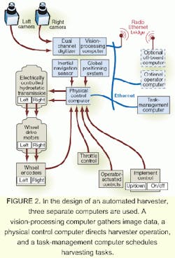
In the design of the harvester machine navigation system, three separate computers autonomously guide the Speedrower. They consist of a vision processing computer to gather image data, a physical control computer to integrate positional data to direct harvester movements, and a task-management computer to schedule the jobs to be performed (see Fig. 2).
To obtain visual data of the field to be harvested, the vision processing computer works in conjunction with two color cameras mounted on the left and right sides of the Speedrower cab to track a crop cut line, detect the end of a crop row, and perceive any obstacles located in front of the machine. Two DXC-151A color cameras from Sony Electronics Inc. (Park Ridge, NJ) capture 768 x 493-pixel images that are subsequently digitized by a Meteor frame-grabber board from Matrox Imaging (Dorval, Que., Canada). The digital data are then fed into a PCI-based Intel Pentium-II PC running the Linux Version 6 operating system from Red Hat (Durham, NC).
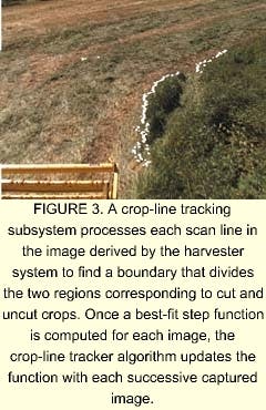
To visually guide the harvester, three interdependent software modules, written in C, analyze the captured images. These modules function as a crop-line tracker, an end-of-row detector, and an obstacle detector. During operation, the crop-line tracking module processes each scan line in the image to find a boundary that divides the two field regions corresponding to cut and uncut crops. After a best-fit step function is computed for each image, the crop-line tracker algorithm updates the function with each successive captured image (see Fig. 3).
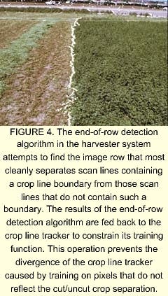
The end-row detector software computes a row corresponding to where the crop ends, to estimate the distance of the harvester from the end of the crop row. When this row is approximately perpendicular to the crop line, the end row of the crop is determined. Scan lines beyond the end of the crop row are then excluded from any further calculations (see Fig. 4).
The obstacle-detection algorithm locates potential obstacles in the field of view of the imaging system. It uses a training image to build a probability density function for combined cut and uncut crops as a function of red, green, and blue pixel values. For each new image, pixels are marked if they are likely to represent potential obstacles (see Fig. 5).
GPS control
Pilarski and his colleagues use a VME-based system linked to the vision processing computer and the task-management computer via an Ethernet interface to control the harvester. At the core of this physical-control computer is the MV162, 68040-based, CPU board from Motorola Computer Group (Tempe, AZ) that runs the VxWorks operating system from Wind River Systems (Alameda, CA).
"We needed VxWorks to turn the mechanical linkage harvesting machine into a drive-by-wire system," says Mike Happold, commercialization specialist/ senior software engineer at NREC. "The controller software running under VxWorks manages all of the harvester functions even while the operator is driving the machine. For example, when the operator turns the steering wheel, the controller senses this action through a steering-wheel encoder and then computes and derives new drive wheel signals for the left and right wheels of the machine," he adds.
The VME-based computer system gathers data from an inertial guidance system, the GPS, and harvester controls such as the throttle, speed, and cutter-head information. In addition, the VME system also electrically controls the hydrostatic transmission of the harvester to move the machine during mowing operations.
To gather positional satellite data, an AG20 GPS from NovAtel (Calgary Alberta, Canada) is interfaced to the VME system using the serial ports of the MV162. Similarly, inertial navigation data are gathered from an E-Core 2000 Fiber Optic Gyroscope from KVH Industries (Middletown, RI), again over the serial ports of the MV162 CPU board. After collection, these data can be used independently or in conjunction with data from the image-processing system to decide which harvesting tasks should take place and in what order.
To control the operation of the complete harvesting system, a second VME-based computer, also based on the Motorola MV162 processor board, acts as the task management computer. During operation, system software runs the camera-based or the position-based navigation systems separately or in combination. The task-management computer cycles through several different states that activate and deactivate a number of appropriate software modules based on triggering conditions.
"Communications among all the software modules are performed over the Ethernet using a software package called Real Time Communications developed at the NREC," says Happold. "This software package allows programs running on the same or different machines with the same or different operating systems to communicate with one another using sockets and TCP/IP," he adds.
During operation, the Demeter system receives position updates from the NovAtel GPS unit five times per second and wheel-encoder and gyroscope data at a rate of 100 times/s. Because the harvester machine operates at speeds to 5 mph, the position-based system needs to send steering-command signals to the control system at about 20 times/s to maintain stable and accurate positioning along the harvesting path.
Field coverage
To construct a path to harvest a crop section, the field-coverage planner module uses the surveyed geometry of the land section and the geometry of the harvester to construct a coverage plan. This coverage plan minimizes the number of passes required to harvest the land section while trying to keep the cutting width of each pass constant.
The plan consists of a coverage path, a speed profile for the machine along the coverage path, and an array of tagged trigger points along the coverage path. The cutting speed of the machine, which varies depending on the field conditions and the type of crop harvested, is specified in the system's task-management script.
Just as an operator-controlled harvester, the Demeter system must reposition itself within the field, a task that is performed by the field-coverage planner. From the surveyed field geometry, the field-coverage planner constructs a perimeter highway path. Repositioning of the system is only allowed on these perimeter highways. To reposition the system, the software directs the machine along a path to the main highway and then moves it along the highway to its final position.
During execution of a coverage plan, the global trajectory tracker is responsible for generating steering and speed commands that guide the machine along the planned coverage path. In addition to all of the responsibilities contained in executing a coverage plan, the global trajectory tracker is also responsible for issuing point turn commands to the machine controller when executing a repositioning plan.
Automated harvesting
The Demeter harvester system has been tested on crops in Imperial Valley, CA; Hickory, PA; and Garden City, KS. In one test, the system autonomously harvested 100 acres of alfalfa in a continuous run that lasted 20 hours. When cutting alfalfa, the speed of the system equals the average speed of a human-operated system, which is in the range of 3.5 to 4.5 mph. Whereas a human operator's performance would decline from this peak when cutting a crop of Sudan grass, the Demeter system maintains the peak-performance level.

"Although the speed of the system currently does not match human performance in the execution of spin turns," says Pilarski, "this turn time is relatively small compared to the time spent harvesting each row." The accuracy of the system's cut depends on whether the GPS or the camera is being used for guidance. Of the two methods for guiding the harvester during a cut, GPS has proven to be the more accurate with an average error in straight-line cuts on the order of 4 to 6 cm.

The accuracy of the GPS guidance system greatly exceeds that of expert human operators, both in individual cuts and in average performance over the course of a working day. According to Pilarski, farmers who have assessed the results of the GPS have remarked on the perfection of the cuts. Harvester use, however, mainly has been confined to the flat, rectangular fields found in Imperial Valley, CA. Future testing will be conducted in hilly terrain and in circular fields.
The performance of the camera system varies with crop type, field contours, and lighting conditions. The average error in the cut produced by the camera system falls within a range of 5 to 30 cm, with the lower number of the range corresponding to ideal conditions: good lighting, a flat field, and thick crop. Because the camera system is following a cut line and is bounded by land-section borders, these errors do not result in missed crop.
As with most automated systems, low failure rate and low cost are key to moving the technology into the marketplace. By using two complementary guidance systems made of components available off the shelf, a practical automated harvesting machine has been developed. "Future systems will improve the obstacle-detection capability and produce a system with graceful failure detection to reduce the impact of inevitable component failures," says Pilarski.
_________________________
Company InformationEncoder Products CompanySandpoint, ID 83864Web: www.encoderprod.comKVH Industries
Middletown, RI 02842
Web: www.kvh.com
Matrox Imaging
Dorval, Que., H9P 2T4 Canada
Web: www.matrox.com/imaging
Motorola Computer Group
Tempe, AZ 85282
Web: www.mcg.mot.com
National Robotics Engineering Consortium
Pittsburgh, PA 15201
Web: www.rec.ri.cmu.edu
New Holland North America
New Holland, PA 17557
Web: www.newholland.com
NovAtel
Calgary, Alberta, T2E 8S5 Canada
Web: www.novatel.ca
Red Hat
Durham, NC 27713
Web: www.redhat.com
Sony Electronics
Park Ridge, NJ 07656
Web: www.sony.com/professional
Wind River Systems
Alameda, CA 94501
Web: www.wrs.com