Vision system checks magnets
To produce the permanent magnets used in hard disk drives, servomotors, loudspeakers, and stepper motors, a complex pressing, sintering, and grinding process is used. In this process, the grinding tools used to obtain the magnet's tight dimensional tolerances can result in chipping and grinding. To control quality, every magnet is individually checked prior to shipment. Oversized, undersized, deformed, cracked, and dirty magnets are rejected. Previously this inspection was performed manually using mechanical calipers and visual inspection.
To automate this inspection process, CCD Photonics Ltd. (Espoo, Finland) has installed a machine-vision inspection system at Neorem Magnets (Ulvila, Finland). Rather than purchase off-the-shelf cameras and frame grabbers to perform this process, however, CCD Photonics chose to build a 5150-element linear-array-based CCD camera controlled by two MC68332 microprocessors from Motorola (Austin, TX). One processor acts as the master controller and measures the external dimensions and shape of the magnet parts passing the inspection gate on a conveyor belt; the second processor checks for the presence of internal cracks and dirt.
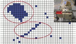
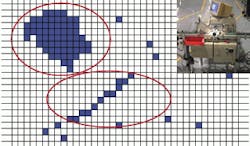
To automate the process of magnet inspection, CCD Photonics has installed a machine-vision inspection system at Neorem Magnets (top). To detect cracks in the manufacture of magnets, a chain of 12 contacting dark spots are regarded as one crack (bottom). The upper ellipse is regarded as a dirty area due to its form factor.
In operation, light rays from a high-frequency fluorescent lamp are reflected from the magnet surface and focused onto the camera's CCD detector using an objective lens with a 40-mm focal length. The camera is tilted at 37° from the conveyor belt, and the light rays from the lamp are partly rejected using a thin curtain blade.
Because the optimal state of the upper surface of the magnet is perfectly flat after grinding, the imaging system must observe deviations due to edge chipping, cracks, and dirt. Some light rays will be reflected from the magnet's surface. However, other rays will be absorbed by the matte surface of a chipped edge or by dirt and result in no reflection in the direction of the camera.
While the appearance of normal grooves is regarded as basic noise, which is not taken into account, the dark spikes, which have the contrast of double the noise level, are regarded as indicating possible cracks or dirt. To recognize whether a crack is present, the identification algorithm must distinguish between separate spots and those spots contacting each other. This is accomplished by recording the positions of dark points during every CCD scan. By recording a data map of each image, the algorithm embedded in the camera can determine chains of contacting dark spots that are computed as either cracks or dirty areas on the magnet.

