Standards ease system integration
Thanks to a number of standards, interfacing digital cameras to frame grabbers and computers will become much easier.
By Andrew Wilson, Editor
Members of the Camera Link, GigE, GenICam, and European Machine Vision Association (EMVA) 1288 standard committees have all made great strides in the past year to make specifying and interfacing these cameras to machine-vision systems more “plug-and-play” compatible. While Camera Link remains the de facto standard for high-speed cameras, improvements have already been made, including the addition of a small Camera Link connector and, this year, the addition of power of Camera Link.
Likewise, as the GigE Vision standard reaches finalization, camera vendors will be able to take advantage of the three years of work that Pleora Technologies and others have made (see Vision Systems Design, January 2006, p. 47). To ease systems integration, however, much work still needs to be accomplished in both the use of standard application programming interface (API) and camera specifications. To this end, the EMVA has currently two efforts underway-the GenICam and EMVA 1288 standards-that promise to bring an end to custom APIs and specifications from sensor and camera vendors alike.
Power Camera Link
Since the Camera Link standard was adopted in 2001 by the Automated Imaging Association (AIA), the Camera Link Committee of the AIA has wanted to incorporate smaller connectors and add camera power capability. Now, with the mini-Camera Link connector finally approved, vendors such as Active Silicon, which offers small PMC-based frame grabbers, will be able to offer Base, Medium, and perhaps Full configurations on single PMC boards. In the past, the size of the MDR-26 connector limited the use of PMC frame grabber designs to the Base configuration, which only requires a single connector. Multiport Camera Link frame grabbers will also benefit. The mini-Camera Link connector will make it possible to have up to four cameras on one board.
According to Steve Kinney, product manager at JAI Pulnix, both 3M and Honda are now making connectors for the smaller pin-for-pin compatible mini-Camera Link connector. Pin-for-pin compatible with the larger MDR-26 connector, the new connector allow systems developers to fit smaller connectors on both boards and cameras. “While the original Camera Link specification allowed cameras up to 10-m to be interfaced to frame grabbers at 40-MHz clock rate,” says Kinney, “we realized that a number of vendors now offer products with 66- and 85-MHz clock rates.”
Rather than dictate a specific distance and data rate to these vendors, the AIA now requires vendors to specify the maximum length that the cable will work at a specific clock speed. “While supporting longer cable lengths may require more expensive cables,” says Kinney, smaller, lighter cables can be used with shorter camera-to-computer interfaces.” Appendix D of the Camera Link specification will include detailed electrical specifications and skew diagrams so that cable manufacturers can specify the maximum length of such cables at clock speed of 85 MHz. Camera Link users will benefit from a wider selection of products to fit their application needs.
At present, the Camera Link standard does not allow power to be delivered over the same connector as image data or camera control signals. But last year, CIS showed a prototype VGA camera to the Camera Link committee that incorporated a miniature Camera Link connector that included power-delivery capability (see Vision Systems Design, August 2005, p. 53). “Now,” says Kinney, “the Camera Link committee is considering a standard that will add power capability over the Camera Link interface.”
Adding resistance
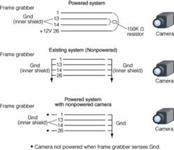
In the original 26-pin Camera Link design, pins 1, 13, 14, and 26 were assigned as ground. To maintain backwards compatibility with this connector, pins 1 and 26 will be reassigned as power lines that will deliver up to 400 mA at 12 Vdc to Camera Link cameras. Kinney says, “Manufacturers wanting to take advantage of the new powered standard will need to incorporate these simple changes into their products.”
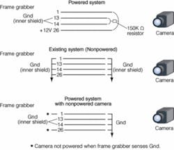
“Simply supplying power from the frame grabber to a noncompatible Camera Link camera would result in shorting of the power in the camera,” says Kinney. To compensate for this, camera vendors will need to place a parallel 150k Ω resistor between the power and ground lines, that is, between pins 1, 26, and pins 13, 14 (see Fig. 1). At the same time, frame grabber vendors will need to provide camera power and a sensing mechanism to measure the impedance across the four pins.
“If no camera is attached,” says Kinney, then there will be an open impedance and no power will be applied. If all four pins are grounded, then a standard nonpower camera will have been attached to the frame grabber and no power will be applied. However, should the frame grabber detect the high-impedance resistor between Pins 1, 26, and Pins 13, 14, then the frame grabber’s on-board power regulator will incrementally apply power to the camera. In case of a shorted cable, this voltage regulator will also be required to sense in-rush current and shut off power applied to the camera. With the mini-Camera Link connector approved last year, Kinney hopes that the “Power over Camera Link (CL)” proposal will be accepted before May 2006. The emergence of software standards such as GenICam will also help systems integrators interface such powered cameras to frame grabbers.
“Self-describing GUIs based on the GenICam standard may be endorsed by the AIA standards committee to allow systems integrators to more rapidly incorporate such cameras into their designs,” Kinney says. “While the 4.1 W of power delivered will suit the majority of products, power-over-CL will not be for all products.” High-performance cameras such as the Pirahna3 linescan camera from Dalsa are specified as consuming approximately 15 W and will still require external power supplies.
Get a GUI
“Today, system integrators are faced with a variety of camera and interface choices,” says Friedrich Dierks of Basler and secretary of the EMVA’s GenICam Standard Group. “These choices range from smart cameras and linescan cameras to area cameras that can incorporate Camera Link, Gigabit Ethernet, USB, and IEEE 1394 interfaces. At the same time, such cameras support a number of vendor-dependent programming and graphical user interfaces (GUIs) that developers must use when building machine vision systems.”
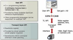
To ease this task, the GenICam standard provides a unified, vendor-independent application programming interface (API) that will allow cameras and machine-vision software to be integrated more rapidly (see Fig. 2). In the first version,GenICam consists of a user API to configure the camera. At its highest level, GenICam also provides a grab API to get images. “Because the GenICam uses a unified, abstract interface for communication between a device and the host,” says Dierks, “any transport mechanism can be used to read and write registers and to stream data.”
The API for camera configuration provides a means by which the system integrator can list camera features and operate sliders, drop down boxes, and other functions that may control camera parameters such as exposure time and pixel format. To do this, camera vendors must build a camera description file of how camera features such as gain map to registers in XML format as described in the GenICam standard. This file is then interpreted by a GenICam interpreter, allowing the data and controls to appear in the API and any generic GUI built on top of this API. To gain access to the camera driver, vendors must supply a transport layer adapter for their products implementing a read and write register function.
GenICam provides a C++-based reference implementation, which in the first version consists of the GenApi module that contains all means to provide the camera configuration API. “Although the reference implementation is not part of the standard,” says Dierks, “it can be used to develop commercial products.” The GenICam group supplies all necessary runtime binaries for using camera description files in applications. “Anyone may use this code at no cost.” says Dierks. “The license for the runtime binaries is BSD-like with the exception that the code may not be adapted.”
The second version of GenICam will allow images to be grabbed via an abstract standardized C++ programming interface that comes as part of the GenTL module. Driver vendors need to implemented that interface as part of a transport layer DLL, which is then loaded by GenICam at runtime. The GenTL module supplies the necessary means to enumerate all installed transport layer DLLs, load them, and bind them to the appropriate camera. The GenApi and the GenTL module will together provide a complete grab and configuration API for cameras based on IEEE 1394, Gigabit Ethernet, or other interface technologies.
Providing a GenApi-compliant camera description file will be mandatory for cameras that comply with the AIA’s GigE Vision standard. For 1394 IIDC-based cameras, which have a fixed register layout, a common camera description file can be supplied. This means that GenICam will provide an excellent unified access to the most commonly used frame-grabberless camera types.
Members of the GenICam standard committee, including Atmel, Basler, Dalsa, JAI Camera Solutions, Leutron Vision, MVTec, National Instruments, Pleora Technologies, and Stemmer Imaging, are currently working on the standard and the reference implementation. Interested readers can obtain the current GenICam standard documents at www.genicam.org. The GenApi module of the standard has been released, with initial compliant products shipping in the first quarter of this year. This module includes the standard API for configuring cameras. The GenTL module defining how to grab images will follow later this year. However, working transport layer example adapters for GigE Vision, IEEE 1394, and Camera Link interfaces are already available.
Stop specmanship
“Anyone who has recently looked at a camera specification will understand the problem,” says Martin Wäny, CEO of Awaiba. “In choosing from the hundreds of cameras from numerous vendors now building CMOS and CCD cameras for machine vision, system developers are faced with evaluating image sensors and cameras based on paper specifications.”
“Existing standards from the broadcasting industry are not suitable for describing performance of image-giving systems in machine-vision applications,” says Wäny. “What is needed are well-defined standards that prevent unfair comparison of specification sheets, reduce support time, and facilitate the developer’s selection of the correct camera or image sensor. With this in mind, Wäny and his colleagues launched the EMVA Standardization Working Group in February 2004.
Now, the EMVA has endorsed its EMVA 1288, a standard that Wäny hopes will become definitive when specifying sensors and cameras. In its approach, the EMVA standard uses a number of modules to specify the parameters of a sensor or camera. While Module 1 specifies the sensitivity, quantum efficiency, dynamic range and noise, Module 2 highlights the linearity, artifacts and defect pixels of the image sensor (see Fig. 3).
“Using a modular approach,” says Wäny, “protects vendors’ investments in measurement equipment and allows further modules to be developed as required. With the first module released at Vision 2005 in Stuttgart, both Basler and PCO have already “self-certified” a number of cameras based on the standard. Basic information required by the standard includes vendor, model, sensor type, resolution (pixel size), shutter type, and maximum frame rate. To compute the specifications of the sensor or image camera, the EMVA 1288 standard specifies a number of measured quantities and a number of quantities that are derived from these measurements.
The standard defines exactly the measurement setup, the measurement acquisition procedure, the parameter computation, and the data presentation. This makes it possible to reproduce the results on different sites such as the manufacturer and the customer. Further, the user knows that all presented data is acquired at the same operating condition-contrary to specifying, for example, sensitivity at maximum integration time, and the dark signal nonuniformity (DSNU) at minimum integration time. The chosen set of mandatory parameters and the presentation of the raw measurement data further permits the customer to compute additional quantities necessary for his application, rather than having to physically test a set of cameras to find out which ones can reach the performance.
“Measured quantities include how much light generates how much signal and how much temporal noise is present at what signal levels,” says Wäny. “From these measurements, derived quantities such as overall system gain, quantum efficiency, full well capacity absolute sensitivity and the dynamic input range can be derived mathematically. To compute these measurements, the ‘photon transfer method’ is used to acquire a series of images by varying the integration time of the sensor or camera. From these measurements, the mean value and temporal noise can be computed independently.
“Spatial noise can be computed using a spectrogram, where an FFT [fast Fourier transform] of the image is performed at dark, 50% saturation, and 90% saturation levels,” Wäny adds. “This provides greater insight into fixed pattern noise than simply indicating PRNU [photoresponse nonuniformity] and DSNU.” Like the GenICam standard, the official draft of the EMVA 1288 standard can be accessed at www.emva.org.
Company Info
Active Silicon
Uxbridge, UK
www.activesilicon.co.uk
Atmel
Saint-Egrève, France
www.atmel.com
Automated Imaging Association
Ann Arbor, MI, USA
www.machinevisiononline.org
Awaiba
Madeira, Portugal
awaiba.com
Basler
Ahrensburg, Germany
www.baslerweb.com
CIS
Tokyo, Japan
www.ciscorp.co.jp
Dalsa
Waterloo, ON, Canada
www.dalsa.com
European Machine Vision Association
Frankfurt, Germany
www.emva.org
JAI Camera Solutions
Glostrup, Denmark
www.jai.com
Leutron Vision
Glattbrugg, Switzerland
www.leutron.com
MVTec
Munich, Germany
www.mvtec.com
National Instruments
Austin, TX, USA
www.ni.com
PCO
Kelheim, Germany
www.pco.de
Pleora Technologies
Kanata, ON, Canada
www.pleora.com
Stemmer Imaging
Puchheim, Germany
www.stemmer-imaging.de


