High-speed cameras target motion analysis
Specifying a high-speed camera requires an understanding of sensor, camera, interface technologies, and software support.
By Andrew Wilson, Editor
In applications such as manufacturing, vehicle-impact testing, flow visualization, and biomechanical analysis, high-speed cameras offer systems developers a means to capture, display, and analyze sequences of digital images. In many automated manufacturing systems, for example, images from high-speed cameras are processed on-the-fly to analyze product integrity at faster than broadcast frame rates. Results of this analysis are used to control production-line pass/fail quality-control systems. In some applications, such as vehicle impact testing, data may be required to be captured at even faster rates. In these cases, sequences of images from high-speed cameras are often stored and used for later off-line analysis.
In the past, specifying a high-speed digital camera was relatively easy. Because of the lack of standard off-the-shelf components, high-speed camera manufacturers were forced to offer fully integrated proprietary systems. While these systems offered image-capture, process, and display capability, they were limited in terms of image-capture speed, the length of image sequences that could be captured, and image-processing capability.
In the past five years, the number of camera choices available has increased tenfold. This has been driven by technological advances in high-speed sensors, cameras, processors, interface standards, and third-party software. While image-sensor and processor developments have increased the system performance of high-speed cameras, the use of standard interfaces such as Camera Link, FireWire, and USB has led to the development of a number of different product offerings, all with different price/performance ratios from camera vendors, frame-grabber manufacturers, and third-party software suppliers. Because of this, integrators can choose from a number of different products to implement their high-speed imaging systems.
CMOS RULES
One of the most important developments in high-speed imaging systems has been the introduction of CMOS imaging sensors. While many people originally thought that these devices would replace CCDs in machine-vision applications, the devices have mainly found niche markets including low-light-level and high-speed imaging (see Vision Systems Design, June 2003, p. 37). These devices offer camera vendors several benefits, including low-cost highly integrated imagers that can be windowed to increase the speed of data captured. To transfer data at high speed from these cameras, vendors have endorsed the Camera Link specification, allowing the cameras to be used with a number of third-party PCI-based frame grabbers.
Despite the benefits of the standard Camera Link interface, at least two manufacturers of high-speed cameras have been faced with a dilemma when developing their cameras. Maintaining strict adherence to the specification was the challenge for Basler Vision Components when designing its A504 series of high-speed cameras. The Micron Technology MV13 CMOS sensor, used in the camera, captures 1280 × 1024 images at 500 frames/s. Because of this, the company redefined the TX26 data valid pin as a video data-transfer pin to interface its product with the full version of the Camera Link interface.
Although not strictly “Camera Link compatible,” the camera is currently supported by a number of frame-grabber vendors, including Coreco Imaging, Datacube, PLD Applications, Epix, IO Industries, and Philips CFT. Interestingly, however, the unendorsed respecification of Camera Link has been adopted by other vendors, most notably Mikrotron in its MC1310/11 series of 1280 × 1024, 500-frames/s cameras. While using two standard Camera Link connectors to transfer image data at 660 Mbytes/s, the camera is “10 × 8-bit Basler A504 compatible,” the company claims.
MASSIVE MEMORIES
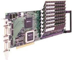
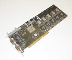
Although attaining very fast data rates is now possible with off-the-shelf cameras, capturing any amount of data for a useful period requires the use of frame grabbers with copious amounts of memory. The Epix PIXCI CL3SD frame grabber, for example, operates in a Pentium 3 or 4 host PC and allows image sequences up to 6.55 s to be captured at full 1280 × 1024 resolution in up to 4 Gbytes of on-board synchronous DRAM (see Fig. 1). On-board memory enables capture at the Basler camera’s full data rate, 625 Mbytes/s, overcoming the bandwidth limitations of the 66-MHz, 64-bit PCI bus. Multiple A504k cameras and PIXCI CL3SD frame grabbers also can be installed in a single computer and synchronized to provide simultaneous multiple views of a motion event.
Using the Epix board, Basler has developed its own stand-alone high-speed imaging system called WatchGuard, which incorporates the A504k camera, the CL3SD frame grabber, and Epix XCAP software. Configured with 3 Gbytes of on-board memory, the system can store a real-time sequence of up to 4.8 s at full camera speed and resolution (see Vision Systems Design, June 2004, p. 10).
Other companies offer both cameras and frame grabbers for this purpose. Photron’s 1280 PCI, for example, uses a 1280 × 1024 camera with an electronic global shutter, operating at 7.8 µs, coupled with a frame grabber to capture images at frame rates to 500 frames/s and at reduced resolutions up to 16,000 frames/s. Interestingly, the camera uses the PanelLink digital output for real-time image transfer and the company’s Motion Tools software that allows the motion of any point within a recorded sequence to be automatically tracked.
Recognizing the need to tightly couple both image capture and storage, many high-speed camera vendors have incorporated on-board high-speed memory into their camera designs. This eliminates the need for additional frame grabbers and allows the cameras to transfer captured data over standard interfaces such as FireWire and USB.
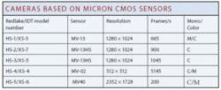
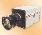
At this year’s Vision 2004 show, held in Stuttgart, Germany, Redlake teamed with Integrated Design Tools (IDT) as its strategic partner for codeveloping the next generation of MotionPro CMOS high-speed digital cameras. According to Luiz Lourenco, CEO of IDT, Redlake will offer five cameras based on a number of CMOS sensors from Micron Technology (see table). First to be released will be the Redlake MotionPro HS-1, featuring 650 frames/s at 1280 × 1024 resolution (see Fig. 2 on p. 40).
Using a partial windowing (region of interest) capability in the new MotionPro cameras, frame rates of greater than 30,000 frames/s can be achieved. The on-board memory, up to 4 Gbytes, allows for capturing image sequences at various frame rates and resolutions. The standard USB 2.0 interface makes for simple integration to Windows 2000, XP, and Max OS X environments and easy downloading of images to the host computer for image analysis.
With the added feature of the triggered double-exposure mode, the MotionPro HS cameras can take two consecutive exposures within a 1-μs time interval. This feature is very useful in particle-image-velocimetry applications, which require capturing the motion of objects moving at very high speeds, such as fuel-spray analysis. Other applications include R&D, production line diagnostics, ballistics testing, and mechanical component testing.
Competing with Redlake’s HS-1 is the pco.1200 hs from PCO. According to IDT’s Lourenco, the 10-bit CMOS imager is the same device used in the XS-3 and features 1280 × 1024 resolution, integrated image memory, and a recording speed of 1 Gbyte/s. Captured image data can be transferred from the camera using customer-selectable standard data interfaces that include IEEE 1394, Camera Link, or Ethernet. Exposure times can be set from 1 µs to 5 s.
Last month, ex-Redlake executive Steve Ferrell emerged with his own company-Fastec Imaging-and a range of high-speed imaging products including the TroubleShooter Model 1000. Fastec Imaging has chosen to use a 640 × 480 CMOS imager in its stand-alone camera that is capable of recording up to 1000 frames/s for periods of 2 s. At PAL and NTSC broadcast frame rates, more than 30 s of images can be recorded. With a built-in USB port, captured image sequences can be transferred to a host PC for later analysis using the company’s CamLink camera-control software.
“In many applications,” says Andrew Sharpe, president of IO Industries, “these cameras are limited in their ability to store image sequences of greater than 10 s. In applications such as missile range testing, for example, 30 s or greater may be required. While this could be attained by adding large amounts of solid-state memory to integrated camera systems, a better alternative is to implement systems using high-speed disk arrays.
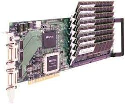
To accomplish this, IO Industries has developed its DVR CLFC Express, a PCI interface board that supports Base, Medium, and Full Camera Link configurations, as well as Basler’s A504 and Mikrotron’s MC-1310 cameras (see Fig. 3). To support continuous uncompressed video at recording rates up to 850 Mbytes/s, the board incorporates five independent, 2-Gbit/s Fibre Channel buses. By interfacing each Fibre Channel interface to up to 126 Ultrastar 15K147 disk drives from Hitachi Global Storage Technologies, the system can support up to 122 hours of high-speed image capture.
Richard Pappa of NASA Langley Research uses this technology in ground tests of solar sail scale models. His goal is to validate structural analytical models of solar sails and to develop an approach to measuring solar sails in space using photogrammetry. Experiments are conducted inside a vacuum chamber where six video cameras are situated. The recorder unit is located outside the vacuum chamber and connects to the cameras using fiberoptic cables and couplers at the vacuum chamber periphery.
The recorder is a single-board industrial computer system running Microsoft Windows XP Pro. IO Industries customized the recorder to record simultaneously from six Dalsa 1600 × 1200 × 10-bits/pixel Pantera SA 2M30 cameras operating at 30 frames/s. Uncompressed video is recorded to hard disk storage for extended recording durations. The recorder uses six IO Industries’ DVR Express CL160 recorder cards, one card per camera. Two Seagate Cheetah 146-Gbyte 10000-RPM Ultra 320 SCSI hard disks are attached to each recorder card, providing up to 70 min of recording time for each camera. IO Industries Video Savant Pro 4.0 controls the video recording, playback, and image processing allowing the operator to view live video from all six cameras while an experiment is in progress.
To support their camera offerings, many camera vendors bundle their products with software designed to support rudimentary functions such as image capture, storage, data transfer, and playback. NAC Image Technology’s Memrecam fx K4, for example, is a self-contained camera with a 1280 × 1024-pixel CMOS imaging sensor and up to 16 Gbytes of memory, allowing megapixel images to be captured for approximately 10 s at 1000 frames/s. Using embedded software, images captured by the camera and stored in memory can be reviewed immediately after image capture on an optional LCD viewfinder or on a PC’s VGA monitor.
SOFTWARE SUPPORT
Developers considering implementing high-speed image-capture systems should also consider a number of third-party software packages. Available from companies such as Norpix, SIMI Reality Motion Systems, and Xcitex, these packages add additional functionality, allowing images captured from PC-based or integrated systems to be further manipulated.
Norpix’s StreamPix package, for example, can acquire live uncompressed or compressed video directly to a hard disk or RAM memory. With StreamPix release 3.10, images from cameras such as Dalsa’s 1M150, Basler’s A504K, and the MV-D1024 from Photonfocus can now be captured at speeds up to 240 Mbytes/s. A range of plug-in modules is also available for time-stamp recording, off-line Bayer filter conversion, histogram, color balance, image de-interlacing, and image overlays.
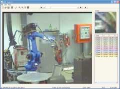
Designed to be used with images captured from FireWire-compatible high-speed cameras, the SIMI Reality Motion Systems motion-analysis software package can store video data in AVI format directly onto a PC hard disk. Using the software, motion-analysis functions such as velocity and angular acceleration can be computed as can image processing functions, such as smoothing and filtering of data with various algorithms including the fast Fourier transform. The company also offers its MatchiX image-processing software for automatic markerless tracking that can automatically track user-defined patterns of different sizes (see Fig. 4).
Supporting more than 40 high-speed and industrial cameras, DAQ systems, and GPS/IRIG receivers, Xcitex’s MiDAS Professional allows systems integrators to independently monitor and control cameras on a network. Using the software, images from a number of industrial cameras, data acquisition systems, global positioning systems, and Inter Range Instrumentation Group timing systems can be synchronously captured. This is especially useful in systems that may need, for example, to show the relationship between inflation of an airbag and valve pressure, between the motion of an athlete and weight distribution, or between the number of revolutions per minute and piston position in an engine.
Realizing the power of harnessing off-the-shelf imagers with low-cost FPGAs, DSPs, and standard network interfaces has lowered the cost of today’s smart cameras. Likewise, the introduction of CMOS-based high-speed imagers, combined with embedded frame grabber- or disk-based memory has widened the choices of the developer wishing to deploy high-speed imaging systems. In the future, as solid-state memory sizes increase and costs decreases, it is likely that many more manufacturers will enter the smart, modular high-speed camera market.Megapixel cameras use compression to increase data storage
In many high-speed cameras, including the FastVision (Nashua, NH, USA; www.fast-vision.com) FastCamera 13 and 40, large amounts of image data are captured and stored in PC-based frame grabbers. Not only does this require large high-speed camera interfaces such as Full Camera Link, it also requires gigabytes of frame-grabber-based, solid-state memory to store just seconds of high-speed image data. To overcome both limitations, FPGA-based image compression can reduce the data rate, the requirement for high-speed interfaces, and the need for large amounts of solid-state memory. In its next generation of cameras, FastVision will implement a real-time JPEG-based compression algorithm in a high-speed camera that will allow the developer to use the vastly increased apparent on-board storage capacity or either Camera Link or USB 2.0 interfaces to transfer real-time data to a host PC.
FastVision’s cameras will be based on the MT9M413 megapixel CMOS image sensor from Micron Technology (Boise, ID, USA; www.micron.com). Using this sensor, 1280 × 1024 × 10-bit data are read out at 500 frames/s, an average pixel data rate of 655 Mpixels/s. Because the sensor has ten 66-MHz taps, on each clock cycle ten 10-bit pixels are output from the sensor on each clock. This is a peak data rate of 660 Mpixels/s.
JPEG compression is performed by dividing the image into 8 × 8 tiles and performing 2-D 8 × 8 discrete cosine transform (DCT) on these tiles. DCT coefficients are then quantized using a quantization table, which is programmable and determines the quality of the resulting compressed image and the degree of compression obtained. The quantized coefficients are reordered into zigzag order. The first coefficient, the DC coefficient, is then encoded using the previous tile’s DC coefficient as a predictor. The remaining coefficients, the AC coefficients, are converted to pairs of zero run counts and values. The length of the zero run determines the code used to compress the value of the AC coefficients.
The encoding scheme uses a variable-length code that is programmable using a table of numbers called the Huffman table. To build a JPEG file, the code stream generated by the compression algorithm is then wrapped in a set of headers and tables, which provide the size of the image, the quantization and Huffman tables used, and other data such as color format, so the image can be restored from the compressed image file. The standard file format for JPEG files is the JFIF image file format.
To perform JPEG compression in hardware at the high data rate provided by the Micron sensor, a number of different methods can be used. One solution is to use off-the-shelf JPEG-compression ICs but this requires multiple JPEG ICs to perform compression at the peak data rate of 660 Mpixels/s. Because off-the-self chips run between 20 and 60 Mpixels/s, implementing a 660-Mpixels/s data rate would require from 11 to 33 of such devices.
A second possible solution is to use IP cores from FPGA vendors such as Xilinx (San Jose, CA, USA; www.xilinx.com). The company’s 8 × 8 DCT core, for example, provides about 150-Mpixels/s throughput when performing the 2-D 8 × 8 DCT. To implement the DCT at 660 Mpixels/s would therefore require about five cores, which would use all the capacity of a 2-M gate FPGA
The solution Fast Vision selected reduces the size of the DCT core by creating a systolic form of the 2-D 8 × 8 DCT, implemented with 1-D eight-point DCTs. To reduce the number of multipliers and adders needed, the fast DCT algorithm is used. Here, the 8 × 8 DCT is implemented by factoring the full 2-D 8 × 8 DCT into sixteen 1-D eight point DCTs. This alogrithm first performs eight 1-D DCTs on the rows and then eight 1-D-DCTs on the columns (see figure). Software for the DCT from the JPEG group implements the eight-point 1-D DCT using 12 multiplies and 32 adds. This can be rearranged into seven steps, where the result of each step depends on the results of the previous step only. This allows the complete 2-D 8 × 8 DCT to be implemented systolically by combining two systolic 1-D eight-point DCTs. This solution produces a column of results each clock cycle, with a seven-clock-cycle latency.
This block can be implemented in a Xilinx XC2V2000 FPGA with about 336 slices, and 12 multipliers, where a slice consists of two flip-flops and some other logic. A 2-D 8 × 8-DCT can then be built with two of these blocks. This takes eight clock cycles, and has a 16-clock-cycle latency. To implement the 660-Mpixel/s data rate, these blocks must run at a minimum 82-MHz data rate (in the FastVision cameras 85 MHz was used).
To achieve further compression, DCT coefficients must be represented with no greater precision than is necessary to achieve the desired image quality. DC coefficients (those with zero frequency) are a measure of the average value of the 64 image samples. Because there is usually strong correlation between the DC coefficients of adjacent 8 × 8 blocks, quantized DC coefficients are encoded as the difference from the DC term of the previous block in the encoding order using a lookup table (LUT) that contains the bits and a count of the number of bits in the code. These data are loaded into a shift register.
AC coefficients are ordered into a zigzag sequence, which places low-frequency coefficients before high-frequency coefficients. This is implemented in a dual-port ping/pong memory in which the data is written in order, eight coefficients at a time, and then read out in opposite order.
AC coefficients, represented as zero runs and values, are then encoded by a Huffman table that provides another set of bits that are loaded into the same shift register. This processing repeats left to right and top to bottom, forming a complete variable-length code bit stream. This is then merged with a header that shows the length of the bit stream. These data can then be stored in memory, making the camera have an apparent capacity of 10 to 20 Gbytes or approximately 40 to 60 seconds of recording time or output from the Camera Link or USB 2.0 port in real time without expensive frame grabbers. Thus, JPEG compression can be implemented in an FPGA at 660 Mpixels/s, in a XC2V2000 Xilinx 2-M gate FPGA achieving a 7-15:1 compression ratio without significant loss of quality.
Joe Sgro, CEO, and Paul Stanton, Vice President
FastVision
Nashua, NH, USA
www.fast-vision.com
Company Info
Basler Vision Components, Ahrensburg, Germany www.baslerweb.com
Coreco Imaging, St.-Laurent, QC, Canadawww.imaging.com
Dalsa, Waterloo, ON, Canadawww.dalsa.com
Datacube, Danvers, MA, USAwww.datacube.com
PLD Applications, Aix-en-Provence, Francewww.plda.com
Epix, Buffalo Grove, IL, USAwww.epicinc.com
Fastec Imaging, San Diego, CA, USAwww.fastecimaging.com
FastVision, Nashua, NH, USA www.fastvision.com
Hitachi Global Storage Technologies, San Jose, CA, USAwww.hitachigst.com
Integrated Design Tools IDT, Tallahassee, FL, USAwww.idtpiv.com
IO Industries, London, ON, Canadawww.ioindustries.com
Micron Technology, Boise, ID, USA www.micron.com
Mikrotron, Unterschleissheim, Germanywww.mikrotron.de
NAC Image Technology, Simi Valley, CA, USAwww.nacinc.com
NASA Langley Research Center, Hampton, VA, USA www.larc.nasa.gov
Norpix, Montreal, QC, Canadawww.norpix.com
PCO, Kelheim, Germanywww.pco.de
Philips CFT, Eindhoven, The Netherlands www.cft. philips.com
Photonfocus, Lachen, Switzerlandwww.photonfocus.com
Photron USA, San Diego, CA, USAwww.photron.com
Redlake, San Diego, CA, USAwww.redlake.com
SIMI Reality Motion Systems, Unterschleissheim, Germanywww.simi.com
Xcitex, Cambridge, MA, USAwww.xcitex.com
Xilinx, San Jose, CA, USA www.xilinx.com
