Designers Analyze Interface Chips for CCD Cameras
As integrated circuits replace discrete components in linear and area-array imagers, designers must still carefully study the system interface functions.
As CCD line-scan and area-array imagers become faster and provide higher resolution, designers face increasingly complex interface tasks when developing camera systems.
FIGURE 1. Correlated double-sampling circuit reduces the thermal, low-frequency, and white noise of CCD imagers. In this technique, the output from the CCD is sampled twice. The first sample is clocked at the reset period and again at the peak of the video portion of the clocked CCD signal. The difference between the two sampled voltages represents the transferred charge. Because each sample also contains noise associated with the device, the process of subtraction eliminates noise from the signal.
Realizing this, major semiconductor vendors are offering integrated circuits (ICs) that aid camera development. For example, analog front-end (AFE) ICs are being designed as interfaces to both linear and area-array imagers and perform functions once relegated to discrete analog-to-digital converters (ADCs), operational amplifiers, buffers, comparators, and digital-to-analog converters (DACs).
"Even though AFE ICs provide an integrated mixed-signal solution for many imaging applications," says Erik Barnes, senior applications engineer at the high-speed converter group of Analog Devices Inc. (Wilmington, MA), "the level of circuit complexity suggests designers must carefully evaluate these devices as they would a discrete implementation." Some factors that must be considered when selecting AFE ICs include the type and speed of the application, the dynamic range required, and, in portable applications, the power dissipation.
CCD interfacing
Driving the development of AFE ICs are sophisticated linear and area-array CCD sensors. Typical of such devices are the IT-P1 linescan sensor and IA-D4-1024 progressive area-scan sensor from Dalsa Inc. (Waterloo, Ontario, Canada). Featuring a dynamic range of 3200:1, the IT-P1 series of 1024, 2048, and 4096 x 1 linear CCD image sensors use proprietary technology to provide four 25-MHz outputs. This four-tap CCD also allows interface circuits to operate at 25 MHz, thereby reducing the need for high-speed interface circuits. Similarly, the 1024 x 1024 IA-D4-1024 sensor offers either one or two 25-MHz taps for handling frame rates to 40 frames/s.
As with most CCD devices, the outputs of the Dalsa linear and area sensors operate with a large dc offset value. For the IT-P1 and the IA-D4-1024 devices, these values are 10 V and 9.1 V, respectively. To establish proper dc bias for the AFE IC, the CCD output is capacitively coupled to the input clamp circuit on the AFE IC with a capacitance many times larger than the input capacitance of the AFE IC.
In the case of the AD9840, an AFE IC from Analog Devices, for example, the device may be coupled to the output of the CCD device with a 0.1-µF capacitor. The device, which features a 36-MHz single-channel architecture designed to sample and condition the outputs of interlaced and progressive-scan CCD arrays, typifies the architectures available from semiconductor vendors.
Correlated double sampling
After the CCD output signal is clamped, a correlated double-sampling circuit is used to reduce the low-frequency and wideband noise of the imager. "To accomplish this noise reduction," says Stuart Boyd, senior marketing manager of the Analog Devices high-speed converter group, "each pixel from the CCD is sampled twice in quick succession."
During correlated double-sampling operation, the first sample is clocked at the reset period before the next pixel charge is shifted out from the CCD; the second sample is clocked at the peak of the video portion of the shifted pixel charge (see Fig. 1). The difference between the two sampled voltages then represents the voltage corresponding to the transferred charge signal. Because each sample contains the correlated noise of the associated pixel, the process of subtraction eliminates this noise portion of the sampled signal.
Although much of the noise from the CCD is eliminated in this way, the analog output from the correlated double-sampling circuit must also be adjusted to maximize the dynamic range of the on-board ADC. In many AFE ICs, including the TAFE IC 1040 mixed-signal-processing IC from Texas Instruments (TI; Dallas, TX), this adjustment is accomplished by a programmable gain amplifier (PGA). Whereas the PGA serves the same function as an automatic gain control (AGC) amplifier, it exhibits superior linearity over that of analog-controlled AGCs.
In the TAFE IC 1040, PGA gain can be adjusted from 0 to 36 dB by programming an internal gain register via a serial port. Because the PGA is digitally controlled with 9-bit resolution on a linear decibel scale, this design results in a 0.09-dB gain step. Applications requiring finer PGA gain resolution (such as camcorders) can take advantage of the Analog Devices AD984x family of parts, which feature a 0- to 36-dB gain range and 10-bit resolution.
Optical black correction
To provide a reference video level for a CCD's dark current, sensor manufacturers incorporate dark or covered pixels into their devices. In the Dalsa linear IT-P1, for example, 32 light-shielded pixels are incorporated into both ends of the photoelement array. In the company's area-array-based IA-D4-1024 image sensor, four arrays of 20 light-shielded columns are arranged at the periphery of the device. Isolation pixels are positioned between the dark and active pixels to prevent the dark pixels from being light sensitive. Consequently, any charge generated by sampling them will be directly related to residual offsets in the signal chain and the low-frequency variations in the CCD's black level.
"In some products, such as color desktop scanners," says Boyd, "black-level reference values are computed by physically calibrating the scanner using fixed reference targets." The resulting offset values can then be digitally programmed into AFE ICs via a digital interface.
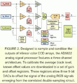
Such is the case with the AD9822, an analog signal processor that features a three-channel architecture designed to sample and condition the outputs of tri-linear color CCD arrays. To calibrate the device, known offset values are downloaded to a set of gain and offset registers; these registers allow three 9-bit DACs to offset the signal of the analog RGB signal emerging from the correlating double sampler (see Fig. 2). The average black level is set in the AFE IC by periodically updating the offset register values. Pixel-by-pixel optical black correction is performed after the AFE IC stage by digital image-processing circuits.
Once a fixed offset is programmed into the offset register, however, the system black level can only be changed by reprogramming the register. To interface to other CCD devices, such as the Dalsa area-array CCDs, the black level cannot easily be calibrated in the same manner. In many cases, such as PC-based still- and video-camera designs, the offset correction value must be altered dynamically within the AFE IC. In such AFE ICs, optical black and system channel-offset corrections are performed by an automatic digital feedback loop. Video data from the light-shielded pixels of the CCD must be compared with a known or desired black level value. To correct this video signal's optical black level, single or multiple DACs are used, depending on the device.
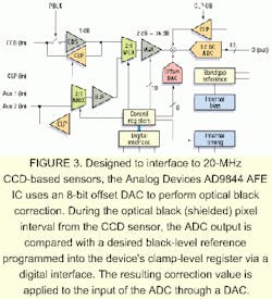
"Designed to interface to 20-MHz CCD sensors, the Analog Devices AD9844 AFE IC uses an 8-bit offset DAC to perform this operation," says Barnes. "During the optical black (shielded) pixel interval from the CCD sensor, the ADC output is compared with a desired black-level reference value programmed by the user," adds Barnes. The resulting correction value is applied to the input of the ADC through a DAC (see Fig. 3). Low-frequency variations in the average black level of the signal can be corrected without the need for external calibration or register reprogramming.
Dual DACs
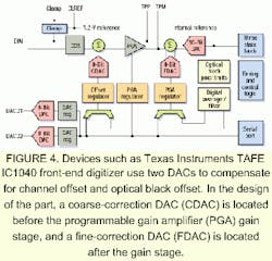
Devices such as the TI TAFE IC 1040 front-end digitizer use two DACs to compensate for the channel offset and the optical black offset. In the design of this part, a coarse-correction DAC (CDAC) is located before the PGA gain stage, and a fine-correction DAC (FDAC) is positioned after the gain stage (see Fig. 4).
During operation, optical black pixels and the channel offset are sampled and converted to digital data by the ADC. A digital circuit averages the data during the sampling of the optical black pixels. The final averaged result is compared digitally with the desired output code that was pre-programmed in the part's black level register. Control logic then adjusts the FDAC to make the ADC output equal to the value held in the black-level register. If the offset is out of the FDAC's range, the error is corrected by both the CDAC and the FDAC.
To correct this error, the CDAC increments or decrements by one CDAC least significant bit, depending on whether the offset is negative or positive, until the output is within the range of the FDAC. The remaining error is corrected by the FDAC. In this way, the AFE IC can be used in an autocalibration feedback mode to compensate for changes in the sampled black level.
"Depending on the type of CCD and its application," says Boyd, "a number of different AFE ICs are available that offer a variety of different resolutions and speeds." For line-scan applications that use devices such as the Dalsa IT-P1 line-scan sensor, which clocks four taps at 25 MHz, Boyd suggests using four 36-MHz, 10-bit, AD9840 AFE ICs, one at each tap. "Sensors such as the Dalsa 1024 x 1024 IA-D4-1024 progressive-scan device that outputs two 25-MHz taps can also use this device," he says.
To accommodate the needs of increasingly faster, high-resolution devices, companies such as Analog Devices, Texas Instruments, and Burr-Brown are expected to increase the speed and resolution of their AFE ICs. At the same time, area and linear sensors that use multiple taps will be handled by higher levels of AFE IC integration that combine two or more AFE IC stages on single devices.
ACKNOWLEDGMENT
The author thanks Erik Barnes and Stuart Boyd of Analog Devices (Wilmington, MA) for their assistance in preparing this article.
Company Information
For information on additional suppliers of CCD camera interface chips, see the 2000 Vision Systems Design Buyers Guide (Vision Systems Design, Feb. 2000, p. 68).
Analog Devices Inc.
Wilmington, MA 01887
Web: www.analog.com
Burr-Brown
Tucson, AZ 85734
Web: www.burr-brown.com
Dalsa Inc.
Waterloo, Ontario, Canada N2V 2E9
Web: www.dalsa.com
Texas Instruments
Dallas, TX 75243
Web: www.ti.com


