Robots, rotary mechanisms and multiple imaging systems
team up to inspect tube-like containers at high-speed.
Cuvettes are tube-like containers with straight sides and a circular or square cross section that are sealed at one end, and made of a clear, transparent material such as plastic. Designed to hold samples such as blood for spectroscopic analysis, these containers are produced using a plastic injection molding process at speeds as fast as two parts per second.
Because the products must be free of defects such as blemishes or tinting that may occur during the molding process, they must be inspected before they are shipped to the end-user. To accomplish this, Envisage Systems (Bletchley, Buckinghamshire, UK; www.envisagesystems.co.uk) has developed two automated systems that each employ five imaging stations to gauge both the cuvettes and their caps for their dimensions, color and any blemishes that may be present.
Checking cuvettes
“Cuvettes can be produced in many different sizes, shapes and of materials that include plastic, glass or fused quartz,” says Mike Phillips, CEO of Envisage Systems. “In this case, it was necessary to inspect dual chamber plastic cuvettes.” These types of cuvettes allow a test sample and a reagent to be placed in the vessel and, then the reaction mixture to be analyzed by an automated instrument, thus improving the efficiency of laboratory procedures.
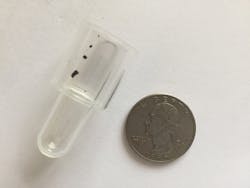
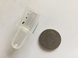
Manufactured by Carclo Technical Plastics (Mitcham, Surrey, UK; www.carclo-ctp.co.uk) in a plastic injection molding machine, the tube-like containers consist of both an outer and inner chamber, the latter of which is approximately 1 mm lower (Figure 1).
Figure 1: Plastic cuvettes are tube like containers that consist of both an outer and inner chamber, the latter of which is approximately 1 mm lower.
“Several tasks must be accomplished to inspect these parts precisely,” says Phillips. First, any molding contamination which may appear in the dome or lower part of the cuvette must be detected. Generally, this is caused by contamination found in the plastic granules used in the production process or dirt picked up during the molding process and appears as black flecks that, if present will affect the accuracy of any tests performed. Should these flecks be larger than 0.2 mm in diameter or if a large number of smaller flecks are detected, then the cuvette must be rejected. Any similar contamination on the outside of the part must also be detected.
Secondly, the distance between the upper and lower chambers of the cuvette must also be measured since, if this height is compromised, the reagent may not react correctly with the sample. Color can also affect any measurements made using these cuvettes.
“If the part has been injection molded at too high a temperature,” says Phillips, “then the part can have a yellow hue.” Such parts exhibiting this must then also be rejected. Other contamination effects may also occur if injection molding machine is contaminated with other polymers. This will result in the parts being cloudy or milky instead of transparent.
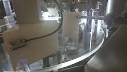
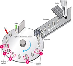
Figure 2: A robot with a custom-built vacuum-plate end-effector first removes cuvettes eight at a time and places them onto a conveyor belt. Since these travel along the conveyor in pairs, they are first singulated before they can be individually inspected by the five inspection stations.
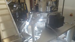
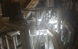
Finally, any flash on the caps that seal the cuvette must be detected. In the design of the transport system, built by Adept Automation Limited (Westcott, Buckinghamshire, UK; www.adept-automation.co.uk), a robot with a custom built vacuum-plate end-effector first removes cuvettes eight at a time and places them onto a conveyor belt (Figure 2). Since these travel along the conveyor in pairs, they must be first singulated before they can be individually inspected by the five inspection stations. To accomplish this, a star wheel is placed in line of the conveyor. This star wheel singulates the parts as they then travel an equal distance apart onto a 600mm rotating plate. This rotating plate is then used to transport the parts at the rate of 2 parts/s under the five imaging stations (Figure 3). A video of the machine in operation can be seen at: http://bit.ly/VSD-PPC.
Figure 3: After a star wheel singulates the parts, they travel at equal distances apart onto a 600mm rotating plate that transports the parts at the rate of 2 parts/s under five imaging stations.
As the cuvette approaches the first imaging station, a photoelectric sensor is used to trigger a 1920 x 1200 ace camera from Basler (Ahrensburg, Germany; www.baslerweb.com) that is fitted with an MML fixed magnification lens from Moritex (Saitama, Japan; www.moritex.com). To image the dome of the cuvette, this camera is placed under the rotating glass platen and illuminated from above with an MDEL-CW70, a 70 x 70mm white LED flat panel, also from Moritex. Images captured by the camera are then transferred over a GigE interface to a PCI Express-based Gigabit Ethernet multi-port adapter installed in an Intel i7-based PC.
To process these images for defects, Envisage Systems chose to use the Sherlock machine vision software from Teledyne DALSA (Waterloo, ON, Canada; www.teledynedalsa.com). Using the software’s graphical user interface (GUI), a region of interest (ROI) is first created over the image of the part to be inspected. Once created, the image is first thresholded and pre-programmed image analysis tools are used to segment and analyze any defects appearing as blobs within the image. If such defects are larger than 0.2 mm in diameter or there are a cumulative number of smaller blobs with a total area that exceeds a certain threshold, then the part must be rejected.
After the dome
After the dome of the cuvette is inspected, it is moved to the second imaging station. Here, the part is backlit using a 70 x 70mm white LED flat panel from Moritex and imaged perpendicularly using a Basler ace camera. Once images are then transferred to the PC, Sherlock blob analysis tools were used to inspect the part for defects.
“One of the difficulties of imaging transparent plastic or glass,” says Envisage’s Phillips, “is that once backlit, the edges of the part will appear dark in the captured image. It is therefore difficult to visualize whether any defects are present in those areas.”
To overcome this, the part is then indexed to a third imaging station where another 70 x 70mm white LED flat panel from Moritex is placed at an angle of approximately 20° off-axis behind the part and imaged using another ace camera, also placed off-axis. “In this way,” says Phillips, “two different angles of the part are captured by the second and third inspection station, thus minimizing the chances of missing any defects that may be present.”
Regions of interest
At the second and third inspection station, captured images are also analyzed for other contaminants that may have been introduced into the injection molding process, resulting in the parts being cloudy or milky instead of transparent. To accomplish this task, four different ROIs are created over both the top and middle of the image of the cuvette and color analysis tools within Sherlock are used to measure the hue of each.
Results of each measurement are then compared and if there is a radical difference between them, the part must be rejected. After this inspection, the part is again indexed on the glass table to a fourth inspection station. Here, the distance between the two different heights of the inner and outer chambers of the cuvette must be measured.
To accomplish this task, the part is illuminated from below the rotating glass plate, again using a 70 x 70mm white LED flat panel. “Diffraction of this light from the interior and exterior chambers of the cuvette then results in an image that exhibits two distinct lines of both the inner and outer chamber heights,” says Phillips.
The resulting image is then captured by another Basler ace camera and transferred to the system’s host PC over Gigabit Ethernet. Here, a region of interest (ROI) is created over the image of the part and measurement tools within Teledyne DALSA’s Sherlock software are used to gauge the distance between the two chamber heights. If the measurement does not fall within a specific tolerance, then the part is rejected. After this inspection, the cuvette is indexed to the final inspection station.
“If parts are not transparent due to injection molding at too high of a temperature, they will exhibit a yellow hue,” says Phillips. “Such parts are not acceptable because they will affect any spectrophotometer measurement when liquid samples are placed within the two chambers.” To ensure that this does not occur, the part is illuminated from the rear again using a 70 x 70mm white LED flat panel backlight. Using a Basler ace color camera fitted with a LM35SC 35mm lens from Kowa (Aichi, Japan; www.kowa.co.jp), images of the part are aquired and then transferred to the host PC over Gigabit Ethernet.
Here, color analysis tools within Sherlock are used to determine the hue of the part and whether it falls within specific tolerances. If not, the part is rejected. Results of each measurement station computed using Sherlock are then accumulated and, should a part fail any of the inspections, it must be rejected. To accomplish this, the PC is used to trigger a programmable logic controller (PLC) that, in turn, actuates a pneumatic reject mechanism located that blows bad parts into a reject bin. Similarly, known good parts are collated into a bin by a second pneumatic actuator.
Capping it off
Just as the cuvettes themselves must be inspected for defects, so too must the caps that are used to seal them in specrtoscopic analysis. To accomplish this, Envisage Systems built a separate machine that uses four machine vision systems. Unlike the system used to inspect the cuvettes, however, the cap inspection system uses a bowl feeder to feed the caps onto the star wheel singulator (Figure 4).
Figure 4: A bowl feeder is used to feed the caps onto a star wheel singulator. Then four inspection stations are used to check the parts for any possible contaminants, measurements that are of incorrect tolerance, color and any flashing.
Here again, four inspection stations are used to check the parts for any possible contaminants, measurements that are of incorrect tolerance, color and any flashing that is present. Because the caps contain concentric rings to partially isolate the chambers of the cuvettes, they must be within a specific tolerance.
After the caps are singulated, they pass under an inspection station that backlights them using a 70 x 70mm white LED flat panel. Here too, a GigE Basler ace camera fitted with a telecentric lens is used to image the part and Sherlock machine vision software tools are used to check for any contaminants that may be present. After this, they are rotated to a second vision station that measures the inner and outer diameters of the two concentric rings of the caps.
After this, the color of the caps is determined in a third station that measures the hues to see if any yellow tarnish is present. Finally, the caps are inspected for integrity and whether any flashing is present using back-illumination and a side-mounted Basler ace camera.
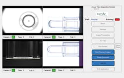
Figure 5: To ensure that the customer can visualize both the inspection process of the cuvettes and the caps, Envisage Systems designed a custom-built front end so that the operator can see the results of the inspection process while a graphic overlay provides information about the regions of the part being inspected.
To ensure that the customer can visualize both the inspection process of the cuvettes and the inspection process of the caps, Envisage Systems designed a unique custom-built front end for both of the machine vision systems using C# (Figure 5). In this way, the operator can see the results of the inspection process while a graphic overlay provides information about the regions of the part being inspected in real-time on the display. Having developed this graphical user interface, the company is currently working to expand this GUI so that it can be deployed in the many other machine vision systems it builds.
Companies mentioned
Adept Automation Limited
Westcott, Buckinghamshire, UK
www.adept-automation.co.uk
Basler
Ahrensburg, Germany
Carclo Technical Plastics
Mitcham, Surrey, UK
www.carclo-ctp.co.uk
Envisage Systems
Bletchley, Buckinghamshire, UK
www.envisagesystems.co.uk
Kowa
Aichi, Japan
Moritex
Saitama, Japan
Teledyne DALSA
Waterloo, ON, Canada
About the Author

Andy Wilson
Founding Editor
Founding editor of Vision Systems Design. Industry authority and author of thousands of technical articles on image processing, machine vision, and computer science.
B.Sc., Warwick University
Tel: 603-891-9115
Fax: 603-891-9297
