Machine vision system measures paint coating thickness on steel products
Companies such as ArcelorMittal (Luxembourg City, Luxembourg; www.arcelormittal.com) JSW Steel (Mumbai, Maharashtra, India; www.jsw.in), and BlueScope Steel Limited (Melbourne, Australia; www.bluescope.com) have two main production costs—steel and coating. Steel production involves products manufactured in continuous coating forms, but painting occurs prior to roll forming steel into an application or building product. Applying too much coating impacts profitability, while not enough coating can lead to potential warranty claims. As a result, controlling the coating thickness on steel becomes paramount for such companies.
To develop a means for controlling the coating thickness on steel for several major steel companies globally, DJH Designs Inc. (Oakville, ON, Canada; www.djh.com), a designer and manufacturer of quality control and testing equipment, partnered with systems integration company Skye Automation Inc. (Stirling, ON, Canada; www.skyeautomation.ca). DJH Designs Inc. developed the equipment and manufactured some of the components, while Skye Automation provided the vision integration and software.

“Quality checks such as color, gloss, solvent resistance, and coating thickness require cut samples off the line,” explains John Henderson, President, DJH Designs Inc. “The system measures very thin film coatings, from half a micron up to about 25 microns.”
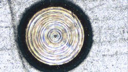
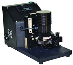
However, before the coating can be measured, an operator must bore into a metal sample (Figure 2), exposing a crater into the paint thickness and the top surface of the coated substrate. After the operator focuses a microscope custom-built by DJH Designs Inc. over the metal sample for clean image capture, the system automatically captures multiple images at different exposures and computationally creates a high-dynamic range (HDR) image (Figure 1).
Used to capture images in the microscope (Figure 3), the VLG-20C GigE color camera from Baumer (Radeberg, Germany; www.baumer.com) features the 2 MPixel ICX274 CCD image sensor from Sony (Tokyo, Japan; www.sony.com), which captures full frame images at 27 fps. Additionally, the camera features a 4.4 µm pixel size, C-Mount lens, and GenICam and GigE Vision compliance.
Also used as part of the machine vision system are an Intel processor-based PC and an incremental encoder from Grayhill (La Grange, IL, USA; www.grayhill.com) that communicates over USB. Communicating to the system over RS-232, an integrated fiber optic white ring light source from Schott (Mainz, Germany; www.schott.com) provides illumination for the microscope-based system.
“The system measures the diameter of multiple layers of coating and craters to accurately measure the thickness of the coating,” says Skye Gorter, President, Skye Automation, Inc. “Lighting control through the computer enables the system to maintain consistency based on the F stop position of the microscope variable to its position—as lighting intensity through the full range of the microscope positions must be sustained.”
After acquiring an HD image, DJH Vpro Software performs a series of steps to calculate the thickness measurements. First, an operator clicks “calculate thickness” in the interface, resulting in the generation of two images, representing two measurement options and sets of algorithms—one for low contrast samples and the other for samples with adequate contrast.
From here, Vpro software uses a series of algorithms to determine the proper measurement solution between the two images. From the HDR image, the software first performs a measurement to find the leading edge of the top coat, and once found, these positions determine the next inspection.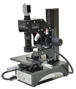
Next, the imaging software calculates the difference between these positions using the number of pixels, based on the camera resolution and the relative position of the microscope, because the crater size changes with the thickness of the coating. The software reads the encoder position of the microscope and calculates field of view, using an advanced calibration routine based on a number of stops through the full range, explains Gorter.
“Once the Vpro software calculates the field of view, a polynomial regression algorithm is used to determine a best-fit curve for the data, enabling the calculation of the exact thickness of the coating based on 360 data points around the perimeter of the metal sample,” Gorter says.
Once ready for coating thickness measurement, as part of the calibration the system converts pixels to real-world units such as microns.
The FOV changes depending on the microscope position as monitored by the encoder. As the field of view changes, the software adjusts for the dimensional change of the image, or in vision terms, the number of pixels representing a unit of measurement, explains Gorter. From a captured image and an encoder reference, the software calculates the thickness based on these parameters to an accuracy of 0.1 micron.
Creating a usable greyscale image from low-contrast samples required an industrial camera capable of providing excellent balance of the color channels according to their spectral response. Edge detection tools applied on a 16-bit high dynamic range greyscale image are possible due to the equivalent quantum efficiency of the RGB response of the camera. The various samples being inspected could be any variety of colors, so having a camera with equal sensitivity means getting optimal contrast regardless of the color combination of the samples. Otherwise, using a color channel gain becomes necessary for calibration of the specific channels, explains Gorter.
“The camera was key to enabling the automated inspection due to the sensitivity of the sensor, which was necessary because of the close color balance between different channels that was required,” he says.
In terms of potential savings for application coating companies offered by such a system, based on an average industrial coating with a cost of $6.75 per liter, and using a conservative consumption of approximately 8 million liters of paint per year, when breaking down the cost of coating per liter, it works out that every micron of coating put down accounts for approximately $1 million, according to Henderson.
“If the system saves even half a micron of coating each year, this means half a million dollars savings. On the other hand, if a company has a 20-micron specification, an upper limit of 22, and lower limit of 18; companies may try to run toward the bottom of that spec to reduce the amount of paint consumed,” he says.
“Anything under that spec, however, opens companies up to huge warranty claims,” he adds. “One rejection from a newly-installed system pays for the cost of the equipment itself.”
View a video further explaining how DJH Vpro software works here: bit.ly/VSD-DJH.
About the Author

James Carroll
Former VSD Editor James Carroll joined the team 2013. Carroll covered machine vision and imaging from numerous angles, including application stories, industry news, market updates, and new products. In addition to writing and editing articles, Carroll managed the Innovators Awards program and webcasts.