CPUs, GPUs, FPGAs: How to choose the best method for your machine vision application
What Is a GPU? FPGA vs CPU? Choose the Best Machine Vision Application
The three most common choices for image processing platforms in machine vision applications are the central processing unit (CPU), graphics processing unit (GPU), and field programmable gate array (FPGA).
CPUs are the heart of traditional desktop computers and laptops. In phones or tablets, an ARM processor that draws less power serves the CPU function. CPUs have larger instruction sets and a large library of native computer languages like C, C++, Java, C#, and Python. Some of these languages have packages that can transfer functions to and run on a GPU.
GPUs have traditionally been used to render the pixels, i.e. the graphics, in video games on PCs. Laptop computers also usually have GPUs. The better the GPU, the better the graphics quality and higher the frame rates. A GPU performs the same function, but in reverse, for image processing applications.
Instead of starting with the conditions within a video game and attempting to render them onto a screen with millions of pixels, in machine vision, millions of pixels are processed down to help software interpret and understand the images. Because they have an architecture composed of many parallel cores and optimized pixel math, GPUs very effectively process images and draw graphics.
The programmable circuits of FPGAs run custom programs downloaded to the card to configure them to accomplish the desired task at lower-level logic that requires less power than a CPU or GPU. An FPGA also does not require the overhead of an operating system.
Machine vision system developers and integrators can get hung up on trying to decide which of these platforms to use before developing the rest of the system. Prototyping the system first can often determine the platform choice. If the math for a particular application doesn’t work on one platform, it likely will not work on any platform.
Setting up the physics of a system (lens, lights, camera, etc.), gathering a selection of images, and testing the math in whatever environment feels comfortable could inform platform choice. For example, some smart cameras include an onboard FPGA to program the camera for different tests. If the prototype runs as intended with a smart camera, an FPGA may be the correct platform for the application and CPUs or GPUs may not require consideration.
Platform criteria
The first and most important criteria for selecting a particular platform is speed. Once a prototyped application works on a test bench, one must determine how many parts the application needs to process per second or how many frames per second of live video must be processed. Generally, for live video, around 30 fps creates a realistic-looking image.
Other aspects of speed, like latency, must also be considered. A system might be able to process a frame in 10 ms but requires 200 ms to get the frame off the camera, 100 ms for the GigE Vision driver to receive the frame and provide it to an application, and another 10 ms to process the frame. In a part inspection application, it may be the case that by the time the frame reaches the application, the part in question has already moved on.
A hypothetical system may have to start queuing part images in order to keep up with the speed of parts moving down a production line. A programmable logic controller (PLC) with deterministic timing would be required to track the position of the parts that generated the queued images so the parts can be pulled off the production line if they fail inspection by the machine vision system.
Start-up latency must also be considered. Not all applications can be left continuously running on a factory floor or allowed a few minutes to start up before a production line begins running. Some applications like outdoor and consumer market systems, for instance a system in an autonomous vehicle, may require powering up and being ready to go in a matter of milliseconds. A machine vision system with several layers of software, such as a CPU with an operating system, may encounter difficulty in meeting short start-up time requirements.
When prototyping speed, tests can be conducted by filming a high-resolution stopwatch. Frames rendered to a screen can be compared to the time displayed on the stopwatch, which allows for easy quantification of latency and determination of how a system may need altering or improvement.
Consideration of how much power a system requires will be critical for some applications and not so critical for others. For applications that run on a mobile device, or on battery-powered hardware like a drone, use of a CPU or traditional GPU may not be appropriate, as these platforms can be power-hungry. Mobile GPUs like the Jetson from NVIDIA (Santa Clara, CA, USA; www.nvidia.com) provide a low-power option, however. A Raspberry Pi-based System-on-Chip (SoC) platform will also have lower power requirements than a CPU.
The reliability of a power source should be considered, especially for drone-based, outdoor, or mobile applications requiring platforms robust enough for handling repeated power interruptions.
Heat and required space for a platform should be considered. Applications built for the factory floor usually have room for a panel that can house all the electronics and a fan to help cool the system. Dusty environments or situations where equipment must be waterproofed, which require appropriate levels of protection (IP65/IP67 respectively), likely will also require sealed panels that can heat up quickly. A larger panel and fanless components will be desirable under these conditions. The more items that must fit into the panel, and the more heat they generate, the more problems the system can cause and the more expensive it can become.
In almost all cases, the chosen platform will need to communicate with other devices, a critical aspect of a machine vision application that may not be considered until the end of the design process. Take, for example, an application that must transmit data for printing. A CPU may be required strictly to communicate with a printer.
Data storage and retrieval requirements may also influence platform choice. CPUs offer the ability to write information to a hard disk. Dealing with memory and persistent storage on GPUs and FPGAs can be more difficult. In some cases, a CPU may be required to augment a GPU or FPGA, strictly to deal with data-related issues. Smart cameras and compact, embedded vision systems can be combinations of platforms that include CPUs, GPUs, FPGAs, and digital processors (DSP).
System dependencies and future proofing must also be considered. Hardware reliability and potential replacement timelines should be estimated. How long will the hardware and software be available for purchase? Does a system allow for scaling up or down if the required processing power changes? How long will technical support be available for the chosen components? Do enough people have the necessary skills to operate the components? Will finding personnel in the future to run the system present a long term concern?
The evolution of chosen components and whether they will fulfill system requirements in the future should be considered. If the engineers behind a line of FPGAs or GPUs develop future generations of hardware with a mind toward solving a specific challenge a machine vision system will encounter, that may speak in favor of adopting those FPGAs or GPUs for an application. If a hardware vendor tries to engineer for a different problem, and ignores the needs of a specific application, that may be a strike against using that vendor’s line of hardware.
Considering requirements for custom code development to create workarounds helps future proof a system. The more custom code a machine vision application requires, the more potential the system has to develop bugs, which is a downside. However, you also want the ability to customize and extend if you need to make the application work for the end user for the long run. If a vendor tool for a particular platform offers a solution to a problem today with little to no custom code, but custom code may be added if and when required, that may be a reason to adopt the platform.
User interface requirements can often be overlooked as criterion for platform choice.Most systems end up having to communicate on some level to a person.Pixel processing can be 100% correct, but if the system cannot communicate information to anyone, the system maybe inadequate to perform a task. CPUs have the best tools for developing user interfaces.Systems based on a GPU, FPGA, or CPU/GPU combination can be designed without a user interface and instead provide summary information via web pages, for purposes of monitoring results.
No singularly correct answers for any machine vision task exist. However,a sample of three different machine vision systems demonstrates how considerations of platform criteria drove the design of those systems.
Welding viewer
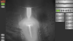
Artemis Vision (Denver, CO, USA; www.artemisvision.com) was contracted by Melt Tools (Portage, MI, USA; www.melttools.com) to design a welding viewer primarily for classroom usage. Welding involves very bright lightin the middle of the field of view and dark surroundings/background, requiring high dynamic range (HDR) imaging to simultaneously reveal the background and the detail at the weld location (Figure 1).
The application required taking multiple exposures at different exposure times and stitching the images together to render a single frame that displays the different lightlevels. Thirty fps output was required to produce smooth video. The system was first prototyped on an Intel (Santa Clara, CA, USA;www.intel.com) i7 CPU. Each input frame required 30 to 35 ms to process, which meant a combined, processed frame was output every 60 to 70 ms. The speed was too slow to support a 30 fps output rate, which required 30 to 35 ms per frame, and so a CPU was not a viable platform for the application.
Moving to a multi-core server and parallelizing the algorithm was considered, as was putting the algorithm onto an FPGA. The customer wanted a system suitable for classroom usage, however, so the system required construction with hardware already present in the engineering classroom.
The computers in the classroom had fairly powerful GPUs to render images for engineering software. The option of putting the HDR algorithm onto the GPU made the most sense.
The algorithm was implemented in CUDA onto a middle-of-the-road NVIDIA graphics card. The GPU processed a frame in 5 to 6 ms and copied a frame to GPU memory in another 5 to 6 ms. No additional hardware other than the camera itself was required to create the welding viewer.
3D laser profiler
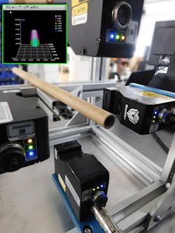
3D laser profilers need fast processing to support high line speeds. For 1000 pixels across the field of view perpendicular to the axis of travel, the optimal system will capture square profiles. With a 1000 mm field of view across with 1000 mm of travel, the system should be able to process 1000 frames to get 1 mm/px resolution, typically working out to multiple hundreds of hertz or frames per second (Figure 2).
A quick boot time is required to allow a 3D profiler to adequately capture and process images of parts in motion. Deterministic timing to avoid the use of an encoder and queuing parts makes the system simpler and easier to put together and debug.
The ability to get direct in/out to GPU memory poses a challenge for employing a GPU with a 3D laser profiling application. GPUs designed as components for PCs do not require an operating system but are most easily used via that CPU’s OS. FPGAs are therefore typically seen as a platform for 3D laser line profilers. The FPGA provides speed, deterministic timing, quick boot time, and reliability.
Dimensioning system
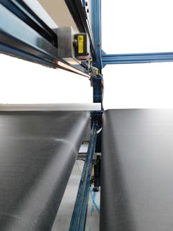
A customer that runs sheeted material wanted to take dimensions of various-sized boards. A measurement time of two seconds was required. The line ran at 120 feet per minute. The dimensions of the boards were from 4 x 4 feet up to 4 x 8 feet and the system needed to detect chips on corners and edges.
An operator interface was required so the board type could be changed and, as with any industrial system, a user interface would be needed to provide error messages if the system wasn’t functioning properly.
The system was first built off a CPU, which ran too slowly. Taking the board dimensions and computing whether corners and edges were complete was taking around 5000 ms. The edge and corner algorithm took the bulk of the time.
Cropping down the number of pixels that require processing by specifying a region of interest (ROI) can increase an application’s speed. A system was implemented to crop out limited edge and corner ROI. With tightly-cropped regions for verifying edges and corners, the compute time was reduced to 800 to 1200 ms. The change to the algorithm made it possible to keep the application on the CPU-based platform (Figure 3).
Conclusion
As these examples show no one-size-fits-all platform for machine vision applications exists. Many variables influence whether a CPU, GPU, or FPGA—or some combination of the three—should be selected. Smart cameras may employ CPUs, DSPs, or a combination of CPU and FPGA. A broad range of options regarding power consumption and processing speed may exist within a single platform. Best performance determines the correct solution.
Tom Brennan is the President of Artemis Vision (Denver, CO, USA; www.artemisvision.com).
Related stories:
IP cores boost machine vision system performance
Understanding the latest in high-speed 3D imaging: Part one
How to get started with deep learning in machine vision
Share your vision-related news by contacting Dennis Scimeca, Associate Editor, Vision Systems Design
About the Author

Tom Brennan
Tom Brennan is president and founder of Artemis Vision (Denver, CO, USA), which builds machine vision systems for automated quality inspection and optimization for manufacturing and logistics. Brennan is an A3 Advanced Level Certified Vision Professional and is the American Society for Quality's (ASQ) 2021 Hromi Medal recipient for outstanding contribution to the science of inspection and advancement of the inspection profession. He has led the design of many successful machine vision systems for many industries. Brennan got his start in the vision industry designing machine vision vehicle detection algorithms as a research effort for the DARPA Urban Challenge. He holds a BSE in Computer Science from Princeton University.