Introduction to Motion Control for Vision Professionals, Part 3
Mike Fussell
Welcome to the final installment of a three-part series covering the essentials of motion control for vision professionals. The previous articles covered the key specifications of motion control devices, and those specs were impacted by different motor, drive, bearing, and encoder types. This article demonstrates how that knowledge can be applied to optimize the design of real-world vision systems. It will examine a vision-guided laser ablation system and a high-magnification automated optical inspection system, explaining how the functional requirements are translated into specifications that can be used to select the ideal motion control components for each application.
Vision-Guided Laser Ablation System
A reliable conductive path between metal parts of an electronic device's casing is critical for achieving its specified electromagnetic emission performance. Selectively removing nonconducting anodization from aluminum parts to create a conductive path between parts is a common manufacturing technique. Automating this procedure can improve manufacturing yields and throughput. A vision-guided system that can accept a mix of randomly oriented parts is ideal for a high-mix, low-volume production environment. It improves production efficiency by eliminating many time-consuming setup steps like changing positioning jigs when switching between different product parts.
To successfully deliver the desired improvements in first-pass yield and production efficiency, the motion control components of this system must fulfill the following key functional requirements:
- Rapidly move a heavy laser scanning head and camera across X and Y axes to locate target parts within a 200- × 200-mm area covered by the laser’s scanning head.
- Cover a large area so that many parts can be ablated in a single batch.
- Position the laser along the Z axis to a target height with a precision of 0.1 mm to achieve optimum focus and maximum power delivery.
- Maintain the Z axis position in the event of power failure.
- Automatically detect and recover from positioning errors.
Translating Functional Requirements to Component Choices
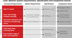
The 200- × 200-mm area covered by the laser’s integrated scanning head is much larger than the 5-mm screw holes, which are the system’s target, resulting in a low accuracy requirement on the X and Y axes. This provides design freedom to prioritize other specifications. Maximizing the number of parts that can be processed in a single run requires a large working area. X and Y stages must therefore have sufficiently long travel to cover the working area (Figure 1a). Recirculating ball bearings are a good choice for long-travel stages in production environments. They can support large cantilevered loads and have long service lives, which reduces long-term maintenance costs and unplanned downtime. Wiper seals surrounding the recirculating bearings provide ingress protection from potentially damaging debris.
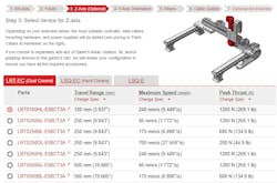
The next key functional requirement is speed. The system must move the laser scanner and fine guidance camera from one screw hole to the next, pausing at each hole to perform the ablation operation. The ideal balance between maximum speed and acceleration is different for every application. Over the short distances between target screw holes, high acceleration will contribute more to throughput than maximum speed. For high acceleration from fixed position, a stepper motor drive is recommended as these motors produce much higher torque at low speeds than servo motors that would require gearboxes that add complexity and cost to the stage. A lead screw or belt drive are both cost-effective options for longer-travel stages, however the higher peak thrust of a lead-screw-driven stage (Figure 1c) will allow faster acceleration of the heavy laser scanning head.
The narrow focus range of the laser necessitates greater positioning accuracy in the Z axis than the X or Y axes. The vertical orientation of the stage must be considered since the load will be lifted by the stage, rather than simply sitting on the stage. In this vertical orientation, the thrust generated by the stage must be sufficient to lift the combined mass of the laser scanning head, attached camera, and lighting components. A stepper motor and lead screw drive is an excellent choice thanks to the high low-speed torque of stepper motors relative to servo motors and the low backlash of lead screws relative to belt drives.
Ensuring the laser assembly maintains its Z axis focus position when unpowered requires a self-locking stage. Linear motors require power at all times to hold their loads, while coarse-pitch lead screw and ball-screw-driven stages can be back-driven. A fine-pitch lead-screw-driven stage is therefore recommended.
The vertical orientation of the stage introduces an additional design consideration compared to stages used in a horizontal orientation. In this system, the mounting of the laser scanning head and vision guidance components will produce cantilevered loading of the focus stage (Figure. 3). The bearings must not bind as the resulting friction may cause the motor to stall. Roller bearings or recirculating ball bearings will perform much better under cantilever loads than plain bearings.
The balance between price and performance must also be considered. Over-specifying a system can greatly increase its cost without delivering any meaningful improvements in its functional performance. Selecting stages with specifications closely aligned to the functional requirements will keep costs in check. Encoder feedback can provide a more cost-effective solution to guaranteeing that 100% of the target screw holes are processed than selecting more expensive stages with a performance buffer. Encoders enable automatic compensation for slipping or stalling of a system that is operating close to its performance limits. Since direct position measurement is not required, motor encoders are the most cost-effective option. Once the system requirements and specifications are defined, online tools like Zaber’s (Vancouver, BC, Canada; www.zaber.com) XYZ gantry configurator (Figure 4) make designing a system to meet those requirements easy.
The vision guidance system uses two 2.3-MPixel, 30-fps USB 2.0 cameras. One camera is stationary and mounted above the system to detect the boundaries of each part. A second camera is mounted beside the laser’s scanning head and moves with it to provide fine guidance for the laser’s galvo scanning head. LED bar lights provide illumination for the coarse positioning camera while an LED ring light surrounds the fine positioning camera.
Like many industrial systems, the machine vision and motion control elements of this system are dependent on each other for their effective operation. Neither can operate independently of the other. Without input from the coarse-guidance camera, the motion control system cannot position the laser scanning head and fine-guidance camera accurately. Without motion control, the fine-guidance camera and laser can not be positioned over the part to be processed. Coordinated operation of these systems is achieved through software. The application was implemented in Python to support rapid development and ease of updating and adapting the system as requirements evolve. Image analysis is performed using OpenCV, while motion control uses the Zaber Motion Library.
High-Magnification Automated Optical Inspection System
Semiconductor devices like CMOS image sensors (CIS) are subject to stringent quality control processes to ensure they will operate correctly and that the materials and processes used to manufacture them are within specified tolerances. Inspecting semiconductor devices requires high-magnification optics to clearly resolve micron-scale features. Precision motion control is necessary to localize those small features consistently.
A demonstration CIS inspection system based on a Zaber MVR automated microscope was constructed. This system was optimized for low-mix, high-volume inspection of small parts. It shows how the same principles used to guide the selection of components in the large format, high-mix, low-volume system can be applied to the opposite end of the spectrum.
To capture actionable images of the micron-scale features on a CIS in a high-throughput production environment, the following functional requirements must be met:
- The CIS must remain at a consistent distance from the objective lens so that focus is held constant across the entire area of the part.
- The system must have a long service life when operating continuously in a high-throughput environment.
- Key features on the sensor must be reliably positioned to simplify automated image analysis.
- The system must capture sharp, clear images.
- Objectives must not be damaged if power is lost.
Translating Functional Requirements to Component Choices
Inspection systems with high magnification optics pose unique challenges to vision system designers. These systems are extremely sensitive to vibrations. Shallow depths of field of less than 1 μm make finding and maintaining accurate focus much more demanding than with standard machine vision optics.
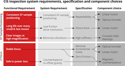
Minimizing motion blur caused by vibrations is essential to capturing sharp images at high magnifications. Vibrations can be reduced by selecting components with high mechanical stiffness. Crossed roller bearings are recommended for high magnification applications because of their higher stiffness and repeatability compared with recirculating ball bearings or plain bearings. Minimizing vibrations with high-stiffness components, which also have very low and highly consistent friction, will greatly improve imaging throughput by reducing the time required for the system to settle after moving between inspection locations or loading the next part to be inspected into the system.
The faster the system can settle between movements, the higher its throughput can be. The high stiffness of crossed roller bearings also improves system performance by ensuring that once focused, the target will remain at the correct focal distance over its entire area. Rapid settling times can also help reduce costs by enabling less expensive rolling shutter cameras to capture distortion-free images, eliminating the need for more expensive global shutter cameras.
Consistently imaging the same point across thousands of inspection targets requires very high repeatability. Linear motor XY stages like the Zaber X-ADR series with nanometer-resolution optical encoders for position feedback can achieve highly consistent results from the first part inspected to the millionth. Stages with a smaller minimum incremental move specification will benefit most from positioning feedback as they will be capable of smaller positioning corrections. Smooth and low-friction crossed roller bearings and low-friction, zero-backlash linear motors can achieve minimum incremental movement distances as low as 20 nm, ensuring consistent results even for 24/7 high throughput applications.
Minimizing unscheduled down-time is critical for industrial processes. Unlike stepper-motor-driven stages, linear motors produce linear motion directly and do not require additional mechanical components to convert rotary motion into linear. This eliminates sources of friction, backlash, and mechanical wear, yielding extremely long service lives. This is crucial for systems like this that will operate continuously at high thrust making many small fast moves between target imaging positions.
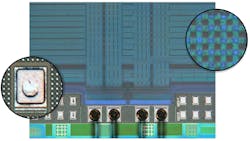
A 24.5-MPixel Teledyne FLIR (Richmond, BC, Canada; www.flir.com/machine-vision) BFS-U3-244S8C-C camera based on the Sony (Atsugi-Shi, Kanagawa, Japan; www.sony-semicon.co.jp/e/) IMX428 CMOS image sensor was selected for its high resolution and large sensor size which delivers excellent detail across a wide area (Figure 4). Reflected darkfield illumination was provided by a Zaber X-LCA4 lighting controller and Zaber MLR3B LED epi-illuminator. The objective lens was a Zeiss (White Plains, NY, USA; www.zeiss.com) EC Epiplan 20x/0.25 HD. Automation of motion control and image acquisition was achieved using μManager software.
Accurate control of the focus shares many of the same requirements as the XY positioning stage. Consistent control of focus requires a small minimum incremental move and high repeatability. These requirements line up well with the capabilities of linear motors. The high stiffness and smooth motion of crossed roller bearings which help minimize vibrations and achieve highly repeatable movement make these bearings an ideal choice here.
Like with the laser ablation system above, the vertical orientation of the focus stage must be considered. Linear motors must remain powered to hold their loads in place, but a self-locking lead-screw stage will not deliver the required repeatability, backlash and minimum incremental move performance. This problem can be solved using a counterbalance to offset the force of gravity and lower the stage gently in the event of a power loss. An adjustable magnetic counterbalance like those found on Zaber X-LDA-AEZ stages is simple to operate, will never wear out, and produces zero friction so it does not impact the accuracy or repeatability of the stage.
Many microscopy applications use autofocus systems to quickly find the best possible focus. Most software-based approaches for autofocus work by capturing a series of images at different Z positions then selecting the image with the highest contrast. Generally, this means overshooting the best focus position, then moving back to it. Applications where a target must be approached from alternating directions with a high degree of repeatability are best served by linear motors which have effectively zero backlash. Optical encoders can further improve repeatability by providing positioning feedback. Further improvements in autofocus performance can be achieved by selecting a focus stage with an integrated controller supporting IO triggering. Such stages like the Zaber X-LDM series can be triggered to step to the next Z position directly via a camera’s digital output line.
Two very different machine vision systems show how the key motion control specifications introduced in part one and the drive and bearing mechanics introduced in part two can be applied to guide the selection of the motion control components that best support the functional requirements of those systems. This knowledge helps vision systems designers make informed decisions to balance the tradeoffs between specifications and build cost-effective and reliable systems that meet their performance targets.


