Inspection system uses magnetic- resonance imaging to check food quality
Inspection system uses magnetic-resonance imaging to check food quality
John Haystead
Contributing Editor
One of the reasons that the food-packaging industry has lagged in its adoption of automated inspection technology is that to detect spoiled products they must undergo a period of incubation so that any bacteria present are allowed to grow. After this period, product must be statistically sampled either by manual or ultrasonic inspection techniques. In addition to being both time-consuming and costly, such procedures also require destructive testing of a portion of the product or its packaging, making 100% inspection impossible.
To address this problem, Intermagnetics General Corp. (IGC; Latham, NY) has developed an automated on-line food-spoilage-detection system based on magnetic- resonance-imaging (MRI) technology. The key distinction between MRI and other imaging technologies is that it allows noncontact, nondestructive inspection of fully packaged product at production rates.
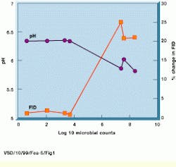
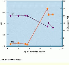
One of the principal indicators of food spoilage is a lowered pH level associated with the proteolysis of proteins and hydrolysis of carbohydrates by contaminating bacteria. Because magnetic resonance relaxation processes, or changes in free induction decay (FID), are directly related to changes in pH levels, MRI can identify such contamination (see Fig. 1).
Using techniques developed for clinical MRI, the IGC system detects and identifies most bacterial organisms that can lead to contamination. Unlike ultrasonic inspection systems that require a transducer to make direct contact with each product, the MRI system allows individual containers to be examined in their final shipping cartons. The IGC on-line inspection system can detect unacceptable food-quality levels in individual packages at a rate of 10 shipping cartons/min.
The Ross Products Division of Abbott Laboratories (Columbus, OH) is taking advantage of the capabilities of MRI inspection. Ross Products makes nutritional products for adults and infants including Similac, Isomil, and Ensure. As opposed to sterilizing finished products, Ross uses aseptic manufacturing processes that take place in sterile environments. "Because sterility rates are lower for aseptic processes than conventional retort-sterilization canning, we needed an extra measure of confidence that 100% of our final product was sterile. The alternative was 100% manual inspection, which would have been impossible," says Timothy W. Schenz, Ross Products Research Fellow.
Clinically modified
Modified for on-line food-inspection applications, the IGC system is based on a MRI system the company originally developed together with SMIS (Surrey, England) for clinical imaging applications. In the system design, a permanent 0.15 T whole-body permanent imaging magnet is used. "In food inspection, using a whole-body magnet allows cases of product to be imaged at one time and allows the system to examine a range of package sizes," says Ian Pykett, IGC vice president of technology development.
Unlike superconducting magnets used in clinical imaging, permanent magnets do not require cryogenic systems to operate. Although superconducting magnets generate greater field strength pulses and higher-resolution images, permanent low-field magnets provided a lower-cost alternative.
Located in a temperature-controlled, RF-screened room on the production floor, the MRI scanner is fed by a conveyor system. "As the magnet is nonconductive, it eliminates the effects of eddy currents and improves image quality," says Pykett. "Access tunnels to and from the magnet act as waveguides, screening the system from radiated interference below the system`s 6.1-MHz operating frequency," he adds. In addition, the horizontal transverse field across the bore of the magnet provides additional signal-reception advantages.
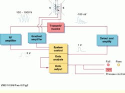
In operation, RF pulses are transmitted to the magnet and on to the sample through an integrated transmit/receive system. To generate the initial waveforms (primary RF and gradient) in the pulse sequence, a PC-based system-control unit is used. Generated at 5 V, these waveforms are amplified by RF and gradient amplifiers to between 100 and 1000 V (see Fig. 2). Each signal or pulse is then applied by magnetic-field gradient coils surrounding the sample. To maximize system sensitivity, the RF coil is designed to be as close to the packing case being scanned as possible.
Magnetic resonance in action
After applying a short burst of RF energy to the magnet, the resulting magnetic-field return signal (or ring) decays (or relaxes) over varying periods of time according to the physical properties of the object. By detecting and converting the return signal back to RF energy, the extent of the response can be detected, measured and related to pH content of the food.
The IGC inspection system uses a variation of this principle known as "spin-echo" imaging. Instead of examining the response of a single pulse, two different directional pulses--a 90 pulse followed by a 180 pulse--are applied. By measuring the time delay between the initial pulse and the time at which the echo is collected, both position (spatial) and composition data can be gathered from the sample.
Once inside the magnet, cases of foodstuffs are exposed to a modified slice-selective MR pulse sequence that allows spatial data to be gathered across the entire case.
Unlike clinical MRI systems, the inspection system does not generate complete images of the sample but compiles a bulk MR signal value from data collected at the points where the 90° and 180° pulses converge. This allows the system to operate at the speeds required for production-line inspection. "It`s a low-spatial-resolution process where measuring the FID relates directly to the pH levels and thus the changes in a spoiled product," says Pykett.
Echos to information
To isolate the low-power returns, the inspection system uses a separate receive coil that also makes the design of the system`s isolation and protection circuitry simpler. Returned analog signals are detected, amplified to 1 V, digitized, and analyzed by the data-analysis system according to the system`s statistical spoilage-detection algorithms. Developed in conjunction with SMIS, the system tracks the running average of signal returns from the items being analyzed and compares these to each subsequent data point.
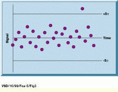
Following the compilation of an initial control data set, consisting of about 30 measurements, the standard deviation of the initial measurements quantifies how far from the mean each new data point lies (see Fig. 3). If a data point falls within acceptable pre-established limits, it is added to the running average replacing the oldest reference. If not, the system flags its source as spoiled. This sliding scale accounts for slight fluctuations in temperature and other environmental variables.
Resulting data can be applied in a number of ways, including a pass/fail output signal to the package-handling system. In cases of a fail, the case is shunted to a different conveyor where a label is affixed indicating which container or containers are contaminated. The conveyor system is controlled by a separate programmable logic controller receiving both RS-232 and TTL-line commands from the inspection-system control console.
The inspection system`s PC-based control and data-analysis console is based on a mix of custom-designed and off-the-shelf hardware. The 19-in. rack-mount unit houses an industrial ISA-bus Pentium computer running Windows NT from Microbus (High Wycombe, Bucks, England) and custom-designed pulse-sequence controller, RF controller, and gradient controller boards. An off-the-shelf digital-signal-processing card performs FIR filtering during data acquisition, while the Pentium processor handles fast-Fourier-transform processing.
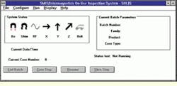
To manage the inspection system, IGC developed a Windows NT-based software interface (see Fig. 4). The interface is designed in three heirarchical layers. One layer allows a plant operator to run the system in fully automatic mode without any knowledge of MRI technology, while a supervisor can define rejection parameters and inspection protocols for any given product family and product type. Experienced MRI operators can access a different layer to design and develop new inspection tasks. The system can also perform self-diagnostic tests at user-defined intervals as part of the routine inspection process.
Pykett expects that MRI will find increased usage in a range of inspection applications and expanded use in the food-processing industry, particularly for aseptic packaging. "Spoilage risk is about 100 times greater in aseptic processing than in traditional canning processes, and one of the major problems is finding a way to rapidly inspect for bacterial spoilage. Right now, there`s no other technology that can detect bacterial spoilage noninvasively."
FIGURE 1. In the MRI food inspection system, changes in the free induction decay (FID) signal of a sample inoculated with a bacteria are shown as a function of the microbial counts and pH of the samples as spoilage progresses. The onset of spoilage, as indicated by the growth of the organism beyond 10,000 counts and a decrease in the pH correlates with the change in the FID signal intensity from the sample.
FIGURE 2. In operation, RF pulses are transmitted to the system`s permanent magnet and on to the sample through an integrated transmit/receive system. To generate the initial waveforms (primary RF and gradient) in the pulse sequence, a PC-based system control unit generates 5-V signals that are amplified by RF and gradient amplifiers to between 100 and 1000 V. Each signal or pulse is then applied by magnetic-field gradient coils surrounding the sample.
FIGURE 3. Following the compilation of an initial control-data set consisting of about 30 measurements, the standard deviation of the initial measurements quantifies how far from the mean each new data point lies. In this example, arbitrary limits have been overlaid on the control chart schematic.
FIGURE 4. Custom-built Windows NT interface software shows the current batch number, product family and type together with the case type (right). The system status window indicates the status of the system. If a diagnostic test is failed, the relevant Icon is shown against a yellow background.
Company Information
Abbott Laboratories
Ross Products Division
Columbus, OH 43215
(614) 624-7677
Web: www.abbott.com
Intermagnetics General Corp.
Latham NY 12110
(518) 782-1122
Fax: (518) 783-2615
Web: www.igc.com
Microbus Group
High Wycombe, Bucks HP10 9QL, England
44 1628 537300
Fax: 44 1628 537301
Web: www.microbus.com
SMIS Ltd
Guildford, Surrey GU2 5YF, England
44 1 483 506611
Fax: 44 1 483 563114
Web: www.smis.co.uk
