System smoothes lumber production
Off-the-shelf cameras and software team to inspect milling, gluing, and compression of laminates.
By Lutz Kreutzer
The recent housing boom has put pressure on the lumber/timber industry to be more efficient. A few decades ago, long wooden beams were constructed from a single tree, cut, and shaped to the particular need of the support panel. Recently, however, timber companies have had to develop new methods to take wood from smaller, softer trees and make it into large, strong beams of almost any length. These “gluelams” (glue-bonded wood beam, or laminates) are a product of Northern Italy’s Ligna KG.
Ligna employees would inspect the wedge cuts at the end of each board and brush the ends of each plank before joining two planks together to form the gluelam. This double brushing was the only way to help guarantee adequate adhesion, but it also consumed both time and glue. By using a vision system to check the glue dispensing, only one end of each plank has to be glued, reducing the quantity of glue and manufacturing costs.
To improve the quality and efficiency, of the gluelam production lines, Ligna turned to Bidac to devise an automated system that guarantees production steps at the gluing station and at the heating and pressing station. The resulting two PC-host-based color vision systems store statistical information locally with remote access and feed quality position measurements to a Siemens PLC that controls the gluing and heating/pressing stations.
Gluelam Production
Gluelam beams are essentially larger pieces of lumber made out of smaller pieces. After they are produced, they can be cut to structurally supportive shapes in the same way that a single board can be shaped, yet with even greater structural strength than a nonlaminate. They can also be made to virtually any length by continually overlapping pieces.
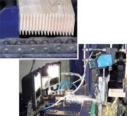
A gluelam begins as a series of raw planks with a length of about 4 m and a maximum width of 26 cm. The planks are cut and dried and then manually checked for natural defects, such as knotholes. The defects are highlighted by hand with luminescent chalk, and the plank continues to the sawing and milling station. At the pollarding station, the plank is automatically cut at any chalk signature, and the remaining defect-free plan is then milled by the wedge milling cutter, creating a uniform pattern of wedges extending outward from the end of the wood. These wedges will later be glued and pressed together to form a longer, defect-free piece of wood, and combined with others to form the final gluelam beam (see Fig. 1).
Wedges and Glue Fingers
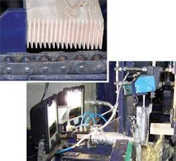
Space constraints precluded Bidac from building two separate machine-vision systems to check the milled ends of each plank and the glue lines used to connect two planks. Therefore, Bidac installed one vision system that would inspect both the quality of the milled end of the plank and the glue dispensing at the same time (see Fig. 2).
The vision system acquires an image of the glued and milled end of each plank using a color UI-1410 VGA uEye USB camera from Imaging Development Systems (IDS). Bidac chose the uEye camera because of its small housing, which includes a standard C-mount for the 8-mm lens, ease of integration with the MVTec Halcon software imaging library, cost, and USB 2.0 output, eliminating the need for a frame grabber at the PC host.
A standard Pentium V microprocessor with 1 Gbyte RAM runs the image-processing software on a Windows XP operating system. For illumination, Bidac used two Osram 70-W Powerlux halide lamps to provide constant, consistent illumination and alleviate the effects of ambient light from the milling plant on the vision-system inspection routine.
The pattern of a glue trace on the surface of a wedge-interfinger must be exact to provide sufficient structural strength in the final gluelam. A glue dispenser, guided by a Siemens SPS S7 PLC, applies six glue ‘crawlers’ horizontally along the end of the wedge-milled plank based on preprogrammed movements and hard fixtures to hold the plank in place.
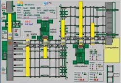
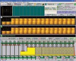
An image of the glued end of the plank is acquired by the camera and passed along a USB connection to the PC’s resident memory for processing. Essentially, morphology and difference techniques were employed to measure the shape of the planks wedges, and the area covered by the glue crawlers versus the area that is not covered by glue (see Fig. 3). If the amount of the coated glue coverage falls below acceptable percentages, or if the software detects a wrong pattern or misses a crawler, the vision system issues a signal across an Ethernet connection to the SPS S7 to repeat the gluing step. If the system determines that the milled end of the board, with the wedges, does not comply with the expected contour, then the vision system issues a different signal to the SPS to have an operator intervene and manually inspect the milled end of the plank. If after a reglueing another malfunction is reported-either caused by the gluing or by a faulty wedge-interfinger-then the area is checked by a human controller and the plank is glued again if necessary or removed from the production line.
If the glue/wedge inspections both pass, then the plank is pressed together with another plank. At this point, if there is a problem during the interfingering and pressing procedure, the following lamella at the glueing station is held in a waiting loop after its release by the vision application.
If delays have caused the glue to drop or run out of the gluing station-again using morphology and difference techniques-the vision system issues an alarm. The gluing station repeats the process to ensure an adequate adhesion. All data, including the number of planks, defects, images, and other statistical data are stored locally on the PC and can be accessed by Ligna quality technicians remotely.
Monitoring Microwaves
After two planks are glued and piled to create a stack of planks that roughly meet the appropriate length and width of the final gluelam, the stack passes by conveyor to the heating and pressing station. The heating/pressing station can accommodate gluelams up to 13.6 m; but gluelams rarely are of a standard length or width, therefore, the outline of the gluelam stack must be detected prior to turning on hydraulic presses and heaters.
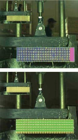
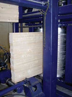
To fix the final form, the unfinished gluelam is pushed into a heat compactor (see Fig. 4). The glue must be dried and pressed in a consistent and careful way. For this purpose, 34 hydraulic lift cylinders equally strain the stack. On both sides of the stack, up to 70 magnetrons (microwave heads) running the length of each side of the heating/pressing station create a homogeneous temperature of 60ºC.
Every magnetron uses approximately 1,500 W; if these units were energized without a gluelam in position, they would incur damage. Thus, a magnetron is only permitted to operate if there is a part of a glued stack in front of it. To activate only the appropriate lift cylinders and magnetrons based on the shape of the gluelam in the station, a second vision system determines the contour of the stack corpus and issues “turn on/off” commands to the controlling PLC via Ethernet connection.
The second vision system is located in front of the heating/pressing station. A VGA uEye color camera with USB 2.0 output looks down on the unfinished gluelam as it approaches the pressing/heating station on a chain conveyor. Standard 500-W halogen lamps are placed around the camera and directed at the gluelam. Additional wattage was required because of the size of the unfinished gluelam.
The application also required that the camera be situated very close to the object, requiring a wide-angle lens and injecting distortion into the image. The Halcon software corrects for distortion based on pre-production calibration routines. As the gluelam enters the heating/pressing station, images of the stack are acquired separately and the software stitches them together using natural artifacts on the gluelam’s surface, such as swirls or color variations. Halcon’s mosaic feature stitches the individual pictures into a single image file.
When a picture of the gluelam is complete, the software uses edge detection to identify the outline of the stack (see Fig. 5). Based on this information, the PLC is instructed to run certain magnetrons and lift cylinders in the prescribed order.
Lutz Kreutzer is marketing manager at MVTec Software, Munich, Germany; www.mvtec.com.
null
