Vision system checks web tension
Customized smart cameras and lighting team with off-the-shelf software to monitor tension during processing.
By Tim Clarke and Graham Long
Web inspection has numerous applications beyond checking colorimetry to make sure inks are properly applied to papers, films, and packages, or performing OCR, template, or geometric pattern searches. Web inspection can also be used to check the physical performance of the printing press, web, or extrusion machine-in particular, the tension of the web during processing.
Poor tension on a web during production caused by bagginess or locally slack edges can lead to wrinkled, laminated foils during the final step of production, or skewed printing, tears, or breaks along with other defects on paper or other products. To reduce scrap in these web applications, York Electronics Centre was tasked by the Engineering and Physical Science Research Council and the Faraday Packaging Partnership in collaboration with Spooner Industries to develop a cost-effective vision system that could measure the tension of the web online and in real time at high speeds.
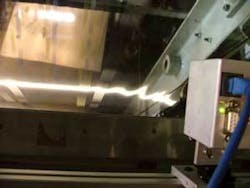
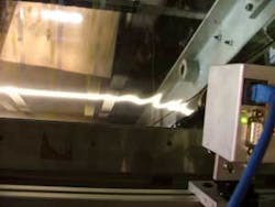
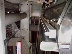
The system uses area array sensors and structured light sources to project and image a line on the web, which is lifted by a cushion of air to take out any slack caused by insufficient web tension during the production process (see photo below). The system measures the variation of the line from the norm to determine the tension of the web and supplies the information in feedback mode to the press or extrusion machine to increase or decrease tension. It also supplies feedback to downstream cutting and trimming machines when breaks and other defects are detected.
Iterative Improvements
The idea was to develop a technique that was generic and useful to a number of industries so they could produce a consistent flat material. This has ramifications throughout the whole supply chain. Downstream operations-such as printing, slitting, cutting, and bending-work much better if the material is uniform, flat, and consistent.
The first prototype system design used multiple KP-M1E/K-S10 analog CCD cameras from Hitachi Denshi, with anamorphic lenses made from low-cost cylindrical concave lenses, mounted orthogonally on an aluminum strut above the web, and a standard fluorescent light masked to create a slit lamp. Frame grabbers in a PC host collected the image data and converted the information to digital data for subsequent mathematical analysis in The Mathworks’ MATLAB running on the PC; however, this led to a processing bottleneck inside the PC at inspection speeds of 2.2 m/s.
Although anamorphic cinema-style lenses stretched the camera’s field of view in the horizontal while shrinking it in the vertical-allowing more web to be inspected with fewer cameras-processing problems persisted. All the processing was done in the PC memory, and there was a bottleneck at the PCI bus. The anamorphic lenses introduced a number of problems, and the ₤1000 lenses were too costly for the project. However, low-cost lenses created significant distortions, which complicated the subsequent processing of the images.
Preprocessing Answers
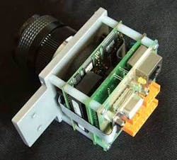
A second solution sought to alleviate the bandwidth and distortion problems while improving the sampling rate of the system and maintaining the coregistration of images from separate cameras for final data analysis. The decision was made to move from analog cameras to DSP-powered VCSBC50 from Vision Components, with a 640 × 480 progressive-scan CCD array sensor and standard C-mount optics (see Fig. 1).
York Electronics Centre engineers programmed these Ethernet-enabled cameras with onboard DSPs to perform simple thresholding on each frame to determine the location of the reflected structured light line within the image frame. The pixel location representing the centroid of the line for each row of the image array is transmitted via Ethernet to an external hub and passed on to the PC that is running the acquisition, MATLAB data-analysis, and visualization program. This thresholding provides more than 80 frames/s, which was a big improvement from the 25-frame/s analog-based system. The increase in speed helped avoid aliasing problems in the measurement process.
After determining the throughput of the cameras based on the specific thresholding algorithm, the cameras were synchronized by connecting them to a common clock generator set to about 80 Hz. Synchronization is important during later data visualization and analysis.
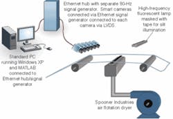
Because only 2 bytes are sent for each column of vertical pixels by the camera to the PC, nondeterministic Ethernet networks provide sufficient performance despite Ethernet’s inherent latency. Using preprocessing on the camera also increases the potential scalability of the system and significantly reduces integration issues (see Fig. 2).
The cameras and high-frequency fluorescent lamp were positioned to detect the reflections of the illuminated line on the surface of the web material to measure the transverse film height and thus determine the variations in the tension profile across the web. In some cases, the web was a 14-µm-thick metal foil and in others a transparent film. A high-frequency fluorescent lamp was used to reduce flicker in the subsequent 80-frame/s image-acquisition system (see Fig. 3).
null
Floating on Air
The film or foil is uniformly deflected by a cushion of air. A special air nozzle system, called an air bar, was designed and fabricated by Spooner Industries. An air blower feeds a plenum chamber that forms part of this system. It is essential for the web material to be subjected to a constant and steady deflection across its width.
As the film or foil travels over this air flow, the material rises in respect to how much slack is present in the web. As the web rises and falls above the blower, the reflected line of light moves up or down inside each camera’s field of view. The displacement of the light line from the norm indicates how much movement has occurred, and MATLAB determines specific height calculations by triangulation based on the pixel values sent from each camera. Each camera’s field of view is approximately 65 mm, which translates to a vertical displacement resolution of 0.14 mm/pixel with a sampling interval of 12.5 ms.
The equivalent tension resolution depends on air pressure, spacing between the rollers, and general machine tension. At a line speed of 131 m/min., the sampling repeats every 27 mm along the web.
The prototype used only three digital cameras to sample the web rather than provide 100% sampling of the web’s tension. The edges were determined to be the areas of biggest concern, so a camera was placed at each edge and in the middle.
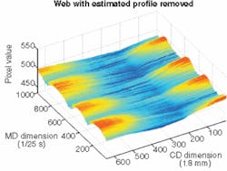
Tension values are generated in MATLAB along with a carpet plot (see Fig. 4). Algorithms can be applied that check to see if the location of the web is within limits. Then a ‘feedback’ signal can modify the process to fix a problem that has been identified, or the web can feed forward to a cutter downstream to remove potentially defective sections.
This system monitors problems on a continuous basis, eliminating the need to take samples off-line for inspection. Its flexibility allows it to be scaled to fit individual applications and retrofitted as needed. A laser-light generator option is available for nonreflective surfaces such as paper. The team intends to continue developing the software and graphic user interfaces.
Tim Clarke is senior lecturer in control engineering and Graham Long is manager at York Electronics Centre, University of York, York, UK, www.yec.york.ac.uk.
Company Info
Engineering and Physical Sciences Research Council
Swindon, UK
www.spsrc.ad.uk
Faraday Packaging Partnership
Leeds, UK
www.faradaypackaging.com
Hitachi Kokusai Electric UK
Leeds, UK
www.hitachi-denshi-uk.com
Spooner Industries
Ilkley, UK
www.spooner.co.uk
The MathWorks
Natick, MA, USA
www.mathworks.com
Vision Components
Ettlingen, Germany
www.vision-components.com
York Electronics Centre, University of York
York, UK
www.yec.york.ac.uk
