Motorized camera and web inspection METHODS DETECT COATING DEFECTS
Motorized camera and web inspection METHODS DETECT COATING DEFECTS
By Eric Peterson
Typical web-inspection systems employ stationary line-scan cameras and use the motion of material being inspected to form two dimensional (2-D) images for later analysis by computer systems. This type of acquisition simplifies optics and lighting design while allowing such systems to find small defects and maintain production throughput.
This process cannot be used for large batches of finished material because no motion is present. However, using web-inspection methods, systems can be configured to find defects as small as 50 µm in areas as large as 1 m2 at rates of two minutes per sample. For example, in a system developed by Proteus (San Francisco, CA) to inspect large areas of coated glass, a motorized x-y stage carries a line-scan camera over the material to be inspected so that a 2-D image of the coating can be captured for analysis.
In operation, a motorized x-y stage carries a custom optical head and line-scan camera through a programmed image-acquisition path with a velocity of 5 in./s. To provide a repeatable imaging environment, the frame used to hold the material under inspection was manufactured of heavy-gauge steel. This provides rigidity for the imaging system, and the steel frame of the easel provides static and dynamic stability and precision in the z dimension (see Fig. 1). To secure the coated material to the easel, Proteus uses a vacuum system.
Line-scan cameras are an ideal choice for this type of system. Linear arrays of up to 10 k pixels combined with kilohertz sampling rates can acquire images at data rates of 60 Mpixels/s. This data stream must be processed on the fly because capturing large 1 X 1-m images at 20-µm resolution would demand large storage requirements.
The CL-C7 4 k line-scan camera from Dalsa (Waterloo, Ontario, Canada) was used in the design of the coating inspection system. The camera outputs 8-bit pixels in 4096 lines at 30 MHz and provides an approximate 3-in. field of view.
To image 1-m2 coating to 20-µm resolution requires 3 X 109 pixels (3 Gpixels). Processing this many pixels in two minutes requires a burst acquisition and processing rate of 40 Mpixels/s (to provide an average 30 Mpixels/s throughput).
PC-based systems lower costs
To reduce the cost of the system, a standard Pentium PC was chosen to control the system. Integrated into the PC is a single-slot PCI-based pipelined image-processing subsystem, the MVC 150/40-PCI from Imaging Technology (ITI; Bedford, MA). The MVC 150/40-PCI includes timing and controls for a separate 40-MHz image pipeline, primary image memory, interface to the host CPU, a slot for one of ITI`s camera interface daughter modules, and a second slot for connection to one of ITI`s pipeline processing daughter modules.
The MVC is built around a 160-Mpixel/s video bus, which connects all the elements in the pipeline, and a crosspoint switch, which supports four channels of 40 Mpixels/s/ channel. The pipeline architecture and the 40-MHz clock rate are key to meeting the performance needs of the coating-inspection application.
The two daughter slots on the Proteus PCI motherboard include an acquisition module that provides the interface and control for the CL-C7 camera and a histogram/feature-extractor computational module (CM-HF) that generates histograms and extracts image features such as size and location based on pixel intensities and patterns in real time. Gray-scale values are streamed into the CM-HF, pass through a look-up table, and are then run-length encoded and written to internal memory, which is read by the host PC.
Pushing pipeline performance
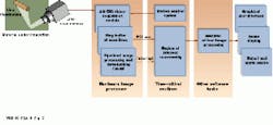
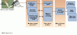
The processing cycle depends on the material being inspected and the nature of the defects. The software environment is designed to take advantage of the pipelined nature of the hardware. In operation, ten line scans are stored to form a buffer image [BUF(N)] that is processed (see Fig. 2). The CM-HF hardware separates the objects of interest and compresses data before passing results to the host over the PCI bus. At the same time, the MVC 150/40 system acquires the next 10-line image [BUF (N+1)]. The host processes data from an earlier analysis [BUF(N-1)] by looking at the gray-scale values of the defect pixels identified by the CM-HF, which are still in the 150/40 memory buffer. All these operations occur concurrently (see Fig. 3).
Software-development libraries from Itexcore were used to develop image-processing algorithms for the inspection system. These contain optimized C functions for the pipeline hardware and reduce the development of complex algorithms. Itex-VIP is ITI`s point-and click graphical user interface software tool, a compiler that generates optimized C code for the MVC 150/40 hardware. Using Itex-VIP shortened the development cycle of the inspection system while providing optimized, structured, and documented C code. Output of the Itex-VIP compiler can be interfaced to user-developed application-specific C code.
Turning results into information
Statistics on the size, location, and gray-scale values of every defect are written to a simple manufacturing control database. At the end of every inspection, the system generates a detailed quality report and a map of the defects on each sheet. These data are used by manufacturing engineers to tailor or modify production processes. They also serve as individualized, sheet-by-sheet quality control reports.
Images from the vision system are output by the MVC 150/40 PCI display generator to a second monitor for operator review. Up to 12 images are kept in a revolving buffer to enable operators to assess process performance. The primary PC monitor is used to display the user interface and system controls, including production control systems and process information.
While this specific system does not provide automatic accept/reject outputs, such capabilities could be designed into such systems. Automation is often made complicated because the material, the defect, and the go/no-go decision are very application- and situation-specific.
Figure 2. Images from the line-scan camera are digitized using the AM-DIG, a daughterboard that interfaces to the MVC 150/40 PCI motherboard. Digitized data are placed into a ring buffer that holds image data while they are processed by the CM-HF pipeline image processor. The pipelined processor performs blob analysis on the buffer image. If any faults are detected, the pipeline image processor posts an interrupt to the MVC 150/40 motherboard and gray-scale ring-buffer data are fed over the PCI bus to image memory within the host PC. Data representing the blob are then reassembled, and blob size is determined and displayed.
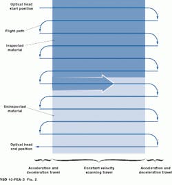
Figure 3. Much like a print head or a paintbrush, both lamp and camera are swept back and forth during material inspection. The x-y motion controller is programmed to move the optical head at a constant velocity over the material. The controller performs all its acceleration, deceleration, and swath incremental motion in the deadbands to either side of the image area. Image data are acquired only during travel over the material.


