Vision-guided robot inserts plane rivets
Using self-calibrating and self-teaching techniques, a large vision-guided robot system punches rivets into airplane metal sheets with high accuracy.
By R. Winn Hardin, Contributing Editor
In the assembly of airplanes, historically manufacturers have manually inserted thousands of rivets to attach sheet-metal skins to airframes. Manual rivet punching, however, has inherently been plagued with various defects. Some defects can compromise operational safety, some unfortunately can result in catastrophic failure, and still others can cause minor operational problems such as wind drag.
For best flight performance, rivets need to be punched flush with the airplane's skin. However, to improve their speed and decrease air resistance, airplanes comprise a collection of elegant curved parts. These sleek aerodynamic shapes of newer airplanes complicate the process.
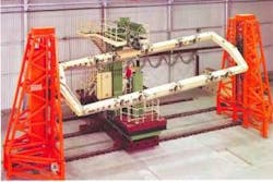
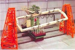
To satisfy their riveting specifications, airplane manufacturers such as McDonald-Douglas and Boeing have turned to companies such as Brötje-Automation GmbH (Wiefelstede, Germany) to provide very large, automated riveting machines. These room-sized robots incorporate both SCARA (selectively compliant automated robot arm) and Cartesian-based elements and are custom built to accommodate specific large assembly operations for airplane wings, bodies, and tails (see Fig. 1).
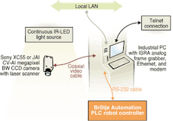
In the past, Brötje has worked with ISRA Vision Systems AG (Darmstadt, Germany) to develop an automated vision system that could insert rivets with x-y accuracy of 0.05 mm. This accuracy is achieved in planarity measurements along curved surfaces of less than 0.5° of arc. Building on its vision experience in the automotive industry installing curved windshields, doors, and other complex assemblies, ISRA developed a self-calibrating and self-teaching robot-guidance system that uses a laser scanner to check planarity while a CCD camera captures images for the x-y placement of rivets using an industrial PC and pattern-matching image-processing software (see Fig. 2).
Different rivets
To obtain high-accuracy riveting in curved surfaces, the ISRA vision system first collects an image of the product using a Sony Broadcast & Professional (Koeln, Germany) XC55 black-and-white 659 × 494-pixel camera or a JAI AS (Glostrup, Denmark) A1 black-and-white 1392 × 1040-pixel camera. Both cameras use square pixels for machine-vision applications and RS-232C serial interfaces. According to ISRA integrated systems business unit division manager Gabriele Jansen, when the sheet-metal part and rivet are of similar surface appearance, the company can supply color cameras to enhance image contrast.
The airplane-wing assembly or other large part to be riveted is illuminated by a custom, continuous-white-light or infrared (IR) light-emitting-diode (LED) source from ISRA. Images of the part are transferred over a coaxial cable at 30/60 Hz from an ISRA frame grabber to an industrial PC and into RAM memory. According to Jansen, the speed of the riveter (one rivet every 2 s) does not push the PC's capabilities.
To that end, ISRA uses an industrial PC and cameras that meet the image-processing requirements of the application without introducing additional costs of leading-edge processors or high-speed read-out electronics, as used in other company high-speed robot vision products. Additionally, the frame grabber, which in this application mainly provides analog-to-digital conversion and buffer memory without on-board processing, provides camera control compatibility, improves system performance, and keeps costs lower.
Robotic guidance
High-accuracy robotic-guidance systems that seek repeatability greater than a millimeter demand precision calibration. Calibration data are based on a template attached to the hard fixture that holds the airplane assembly; these data are used to establish a global coordinate system that includes the position of the robot in relation to the vision system and the part assembly.
The guidance system starts each session by imaging a calibration plate containing an array of drilled holes attached to the hard fixture holding the assembly. Pattern-matching techniques locate the center hole in the calibration plate and set that point as the center of the global coordinate system. The vision system establishes a pixel-to-millimeter relationship using the known dimensions of the calibration template.
In the next step, the guidance system measures the distortion of the holes in the remainder of the assembly to compensate for optical distortion induced by the camera's lens. This parameter increases the measurement accuracy needed by the system for points off the optical axis.
After establishing the robot's position, the vision system locates the approximate position of a drilled locator hole on the airplane assembly. This hole is used by the robot and the fixture as a "zero point" for assembly positioning. Next, the rotation of the part relative to the vision system, which resides just above the robot's rivet punch, is determined by analyzing the distortion of a second hole on the assembly located near the first hole.
From this second hole on to the other holes, robotic guidance to each rivet location initially comes from programmed computer-aided-design data fed in ASCII format into the Brötje programmable logic controller (PLC), which directs the robot's actions. After the robot punch/vision system reaches the approximate location of the rivet's position, the vision system provides final guidance directions. It provides delta values that represent the difference between the actual location of the next rivet in sequence and the initial "zero point." Delta values are fed to the PLC by ISRA software running on the industrial PC.
Rivet adjustments
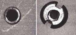
Initially, the airplane assembly is temporarily held together with "tack" or provisional rivets, which are often deformed during the initial punch process. Each provisional rivet has a hole in its middle surface, where the final rivet is inserted. In addition, the vision system uses several reference holes that do not have provisional rivets as 'undeformed' reference holes. These holes help fine-tune the placement of the rivet punch by allowing the guidance system to adjust to the curved surface of the airplane's skin while taking into account the optical distortion induced by the camera's lens.
After calibration, the system collects an image of the next rivet, uses pattern-matching algorithms to find the center hole in the provisional rivet and a nearby reference hole, and calculates the delta value. Based on this, the rivet punch is moved to the correct position, and it inserts a final rivet into the assembly.
"Because the provisional rivets are slightly soiled in some cases, self-teaching was critical to the success of this system," explains Jansen. "To provide this, we needed an imaging system that could detect contrast differences between the rivet and the assembly surface."
To make sure that the final rivet is flush with the assembly's surface, adherence to the surface's specification is checked by the vision system before it inserts the next rivet (see Fig. 3). Accordingly, the vision system triggers a visible laser cross-line scanner in the camera enclosure. The CCD camera collects images at 30 Hz as the 20-mm laser cross-scans (two orthogonal lines) across the skin of the airplane part. System software thresholds the laser line to isolate it from the surrounding image and measures distortions in the line to make sure that the metal skin does not differ from the curved surface of the assembly by more than a 0.5° arc.
If the riveted surface fails to meet specifications, an alarm is sent to the operator via the PLC. Pass/fail data, in general, are stored on the industrial PC's hard drive as an ASCII log file. The data are remotely accessible through either an Ethernet connection in the PC or via a modem, depending on customer specifications. This connection can also be used by ISRA support personnel to troubleshoot the system whenever necessary. Image files of failed operations also can be saved in compressed JPEG format on the PC's hard drive.
Company Info
Brötje-Automation GmbH www.broetje-automation.de
ISRA Vision Systems AG www.isravision.com
JAI AS www.jai.com
Sony Broadcast & Professional www.sony.com/videocameras


