Vision sensor aids PLC system control
Machine-vision/image-processing functions identify wheels despite material, color, and outline variations.
By C. G. Masi, Contributing Editor
Ross Pryor, president of systems-integrator Factory Automation Systems (FAS; Atlanta, GA, USA), says, "Industry pundits have said that general-purpose computers would be taking over factory-automation tasks.The fact is that there are so many issues with operating systems, variability in hardware configurations, and so on, that the programmable logic controller (PLC) remains—by a huge percentage—the industry's standard way to control industrial processes. Eighty to eighty-five percent of new systems being put into industry [rely on] PLC control."
Therefore, when a systems integrator confronts a factory-automation task for which the system needs to have vision, the result is often a combination of a machine-vision system and PLC control. Fortunately, off-the-shelf vision products are available that make connecting a machine-vision system to virtually all factory-automation control equipment—including PLCs—relatively quick and easy.
Factory Automation Systems faced such an integration task when designing a vision platform for wheel-manufacturer Hayes-Lemmerz (Gainesville, GA, USA). "The company was looking to identify wheels," Pryor says. "In its process, after the wheels are quenched leaving the casting mold, they are put on a conveyor, and different model wheels travel down that conveyor. At the end of the conveyor, a robot picks them up and feeds them to an automated saw that removes the flashing on the wheel."
The manufacturer uses two casting machines that can run up to 12 parts simultaneously. "Before installing the new vision system," says Greg Thompson, controls engineer at Hayes-Lemmerz, "we had to either make wheels in single-model batches, or have a technician stand there and push a button to identify the model of every wheel as it came through."
The model number has to be correct so that the robot uses the right saw profile. If the technician keys in an incorrect number, the saw will damage the wheel. The manufacturer's goal for installing an integrated machine-vision system was to make full use of its casting machines' flexibility without adding the error-prone manual identification step.
Design needs
The desired machine-vision system has to distinguish, with better than 99% reliability, which wheel model out of the five is coming down the conveyor line. It also has to contend with variations in material, color, and outline caused by mold flashing. It then has to correctly transfer that information to the PLC that runs the automated-saw work cell. In addition, it has to be flexible so when the manufacturer develops new wheels, the vision-system software can be updated to accommodate the change with minimal effort.
The FAS engineers were looking for four key properties in all of the system components, as well as in their integration architecture. They had to be compact and rugged. From the welded-steel system-support structure to the compact, rugged packaging of the vision processor, all the components were chosen for robustness. They had to be supported by readily available spares. For example, standard lighting fixtures were chosen that would do the job well, rather than specialty devices that might have more closely fitted the application needs. They had to be user-friendly. A spreadsheet-like programming interface was selected because it would be familiar to technicians, instead of picking a, perhaps, more flexible interface using Visual Basic or C. And they had to use the lowest performance technology and cost that worked.
While developing the vision platform, FAS engineers used the simplest, most robust, and easiest-to-support technology available (see Fig. 1). Take, for example, the lighting system. The work area that needed to be illuminated was 21 in. (53 cm) in diameter. The design team selected commercial 4-ft-long, high-frequency fluorescent lights because they were more readily available and less expensive than 2-ft units.
High-frequency fluorescents, which are necessary in machine-vision applications to avoid the flicker of 60-Hz cycling of low-frequency fluorescents with the camera's frame rate, are also more efficient than their low-frequency equivalents. That energy efficiency makes them popular with facilities engineers. Moreover, 4-ft fixtures and tubes are more common in factory supply rooms. Two-foot units, however, are special devices that cost more and are somewhat harder to find. "Even a 4-ft-high frequency ballast is easier to find than a 2-ft-high frequency ballast," adds Pryor.
"We are a foundry," Thompson points out, "which is a harsh environment with high heat, shock, and vibration, and aluminum-oxide dust. To ensure high reliability and maintainability despite the harsh environment, FAS built a vision-system enclosure out of welded steel, rather than with aluminum extrusions and bolts, to physically support the camera and lighting devices (see Fig. 2). This task was harder to build, and the enclosure weighs about 500 lb, but maintenance requirements are lower and reliability is higher," he says.
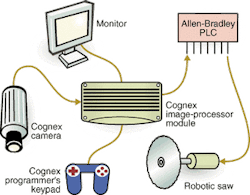
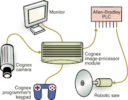
The same design approach extends to the machine-vision hardware and its link to the PLC. The engineers chose an In-Sight 3000 sensor system from Cognex Corp. (Natick, MA, USA) as the vision-application platform. This sensor is a self-contained vision system, complete with camera, programmable image processor, and user-friendly interface. Thompson points out, "It is a sealed module that we just had to bolt in place."
The vision sensor consists of a progressive-scan, monochrome digital camera that scans at 30 frames/s. It uses a 1/3-in. (8.47-mm) CCD that provides 640 × 480-pixel resolution and 256 gray-scale levels. To achieve a 20-in. (508-mm) field of view, the camera comes with a C-mount f/1.3, 8.5-mm-focal-length lens from Edmund Industrial Optics (Barrington, NJ, USA) that is attached to the camera for an object distance of 518 mm.
The camera's video output is delivered to the sensor's 11.52 × 5.61 × 1.79-in. processor module via an RJ-45 cable. This module contains a 4-Mbyte nonvolatile flash memory and a 16-Mbyte SDRAM for image acquisition and processing. In turn, the processor connects to a SLC 5/04 PLC from Allen-Bradley (Milwaukee, WI, USA) by means of an I/O breakout box that holds eight optically isolated outputs that source 24-Vdc logic signals.
Cognex designed the sensor system to be set up by nonengineers and programmed by nonprogrammers. Such features make the vision-system design easier to accomplish for novice engineers, as well as simpler for experienced systems integrators. FAS engineers decided that it was better to install a pre-integrated system and save their efforts for more creative tasks, such as figuring out how to make the entire system more robust and user-friendly.
Keep it simple
The vision system informs the PLC which wheel model is ready for finishing by the robotic saw. The PLC, which controls the entire sawing operation, offers 64 kilowords of ladder-logic instructions through 4096 inputs and 4096 outputs.
The engineers chose a PLC because it is a straightforward and robust controller that is backed by decades of use. A PLC is especially useful for handling industrial-automation tasks. For example, the PLC can be readily interfaced to many factory-floor networking protocols, such as Ethernet and RS-232. FAS engineers, however, decided to use the simplest interfacing scheme of 24-V logic levels to do the job. They knew, from the Hayes-Lemmerz' specifications, that the wheel-identification system had to deal with five wheel types. Furthermore, eight I/O lines were available to connect the vision processor to the PLC.
The simplest way to make the connection was to assign one I/O line to each wheel type. When the vision processor recognizes a particular wheel type, it activates the corresponding I/O line. All the other lines are deactivated. A more sophisticated processing system would have required detailed coding and decoding. The simpler approach was, therefore, to use the I/O lines individually.
Since the original system installation, Hayes-Lemmerz has added more wheel models. The vision system now identifies seven different wheels. "It was easy using the spreadsheet-style programming interface to add the new models," reports Thompson.
"Using the processor's extended I/O, we can go up to 12 lines," he says. Should the company need to extend the system beyond 12 models, they could switch to a more sophisticated I/O coding scheme.
Company Info
Allen Bradley www.ab.com
Cognex Corp.www.cognex.com
Edmund Industrial Optics www.edmundoptics.com
Factory Automation Systems www.factoryautomation.com
Hayes-Lemmerz www.hayes-lemmerz.com


