Telecentric module adds vision precision
Andrew Wilson, Editor, [email protected]
Telecentric lenses are especially useful where a fixed working distance from the object to the lens is imprecise or where other types of optical systems lead to edge vignetting. By using telecentric lenses, the principal ray of the object being imaged emerges parallel to the optical axis, and, as a result, defocusing the system causes a small change in the magnification of the image. This can be 50X-100X smaller than in endocentric systems.
“While telecentric lenses provide an excellent means for accurate gauging applications, they must be used in conjunction with proper illumination,” says Klaus Eckerl, president of IB/E (Hutthurm, Germany; www.ibe-optics.com). “Indeed, if incorrect lighting is used with these lenses, the benefits may not be realized.” Using diffuse backlighting, for example, may result in light rays reflecting from the object, making the width appear larger or smaller, depending on the object’s distance from the lens. Replacing this backlighting with collimated telecentric lighting, however, can reduce these effects.
IB/E designed and developed an imaging system to measure the diameter of a pin with a known linewidth of precisely 10 mm. In the design of the system, the pin was fixed to a stepper motor at the center of an imaging system that consisted of a telecentric lens with a 16-mm field of view coupled to a CCD camera. Initially, the illumination for the system consisted of a telecentric illumination module that lit the object with parallel light.
After the image was captured by the camera, a simple standard PC-based machine-vision algorithm was used to compute both edges of the pin. “Since the diameter of the pin was known precisely,” says Eckerl, “it was easy to calibrate the system in terms of pixels per millimeter at the nominal distance.”
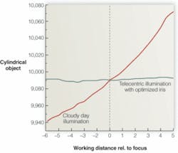
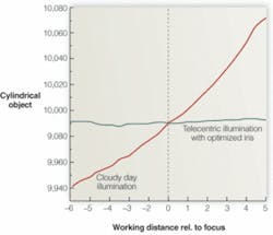
Once the system was calibrated, the pin was moved ±5 mm within the field of view of the telecentric lens. At each position, a measurement of the width of the pin was taken and plotted against the working distance of the lens from the object. After replacing the telecentric illumination module with a cloudy-day illuminator (CDI), this procedure was repeated. As can be seen, the effects of varying the light source are quite dramatic. Using telecentric illumination, the error introduced is less than 2 µm. However, using CDI, the error would be ±0.05 mm (see figure).
“Because these edge measurements are very dependent on the lighting used,” says Eckerl, “system developers must be careful when specifying both lenses and illumination systems.” For this reason, IB/E has developed a series of illumination modules for its range of telecentric lenses. These modules use a power-supply unit that drives a telecentric illumination module consisting of a single LED and diffuser. Available in red, blue, green, and white versions, these modules are coupled to the company’s telecentric illumination lenses to form a complete illumination system.
“Different colors of LED light do not typically affect any dimensional measurements that need to be made,” says Eckerl, “since these measurements do not change with the frequency of the light source. However, when colored surfaces are imaged, different color LEDs and filters can increase the contrast of specific defects.” Thus, by offering modular telecentric illumination systems with a range of fields of view and color options developers can tailor their applications for different part sizes and surface-measurement capabilities.

