Guided Eye
Vision-guided robots debur and measure engine parts in multiworkcell operation
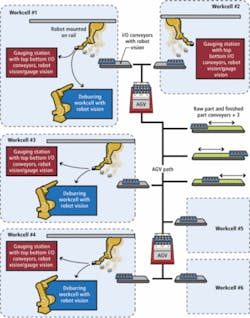
Robots are increasingly used in deburring applications—removing the metal chips and flashing common to machined or cast-metal parts—because they can perform operations faster, safer, and with greater repeatability than manual operators. Diesel-engine part manufacturer EMP has pursued factory automation since the 1990s and in recent years created a new production line that combines six automated machining workcells manned by FANUC robots. The workcells are connected by a small fleet of FROG Navigation Systems automated guided vehicles (AGVs). Ten vision systems guide the robots to parts on dunnage trays, while another four vision systems monitor operational effectiveness, gauge parts, and direct work flow—all without barcodes or any form of standard serialization.
EMP LV and M46 machining and cleaning lines are examples of how automation leads to flexibility, savings, and even reuse. These two lines spread among six different workcells manufacture four different parts used in hydraulic pumps in a workspace totaling approximately 80,000 sq ft, according to Gabe Kluka, lead designer for the production line.
Workers loading full trays of raw parts onto incoming conveyors use forklifts because each part weighs about 50 lb. AGVs pick up a tray of parts from one of three conveyors—one serving the LV line and two serving the M46 line—and follow preprogrammed paths to the first machining based workcell. The AGVs roll the tray of parts onto an incoming conveyor. A vision system guides the robotic arm to grasp the part and feeds the automated CNC machines, in turn. Periodically, the robot samples a part in-between machining operations and takes it to a gauging station, where an auto gauge measures the part and feeds back size information to the machine to compensate for tool wear.
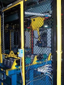
After the machining is finished, the robot passes the part to another robot located in a nearby deburring station enclosure. The deburring robot completes approximately ten water-jet cleaning procedures before replacing the finished part on the tray. An AGV collects the full tray and carries it to an outgoing conveyor next to the incoming conveyor on the east side of the shop floor.
“The system really saved us a great deal of money and floor space,” Kluka explains. “We could avoid a palletized conveyor system, and the AGV conveyor costs were very low. Right now, the LV line produces one part, but we could change that over and reuse 70% to 80% of the capital equipment. The pallets for the AGVs were inexpensive to manufacture, so the whole thing was a cost savings for us, and it opened up the floor so the operator can walk around without having to do a long hike.”
Layered manufacturing network
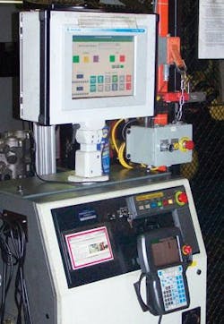
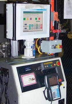
An Allen-Bradley Ethernet/IP network connects and controls each of the six workcells, as well as connecting each workcell back to EMP’s front-office enterprise resource planning systems. Operators control each of the six cells through a local Allen-Bradley VersaView HMI computer. The HMI computer also supervises and communicates with FANUC robot controllers, although robot operation can be effected through FANUC iPendants located at each HMI terminal (see Fig. 1).
“Although the workcells communicate across the same network, we run vision separately on each station,” EMP’s Kluka says. “We’re big fans of parallel. We don’t want a single point of failure. Adam Veeser, one of our automation engineers, did an excellent job of making sure our vision systems and control network functioned independently, yet can talk across the shop floor so the operators and business system can monitor the cell effectively.”
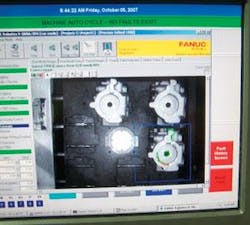
The HMI industrial computer also hosts a Euresys Picolo Pro 2 frame grabber, which has the capacity to receive images from up to four 768 × 576-pixel analog cameras. FANUC pairs up the Picolo Pro 2 with the JAI TM-200 analog 768 × 567-pixel CCD camera as one offering within FANUC’s visLOC family of vision systems for robot guidance. The Picolo Pro 2 provides A/D conversion of image data for porting into the HMI’s main memory, where visLOC software takes over.
Each incoming conveyor has a single visLOC system suspended above the terminus of the conveyor, closest to the workcell’s FANUC robot (R2000i or M710ib/70T). There are 10 incoming conveyors serving six workcells and four gauging stations. Each gauging station uses one camera for part orientation and inspection (see Fig. 2).
Smart system integration
Each M46 tray holds six parts arranged in a circle with a hole in the middle of the tray. Each part is held in a nest that maintains part orientation by ±5° of rotation. The vision system guides the robot within those 5° for the best possible pick from the tray. The trays are blue to provide good contrast between the metal parts and the trays when illuminated with red LED ringlights from Spectrum Illumination surrounding the Tamron lenses. Contrast is further increased by filtering out ambient light by placing Midwest Optical bandpass filters centered around 660 nm in front of the Tamron lenses.
The hole in the middle of the tray allows the three-jaw chuck on the robot’s arm to pick the tray up and transfer it from the incoming conveyor to the outgoing conveyor. The robot uses the same chuck to pick up the individual parts and feed them into each machining station. After the chuck grabs the center of the part, a set of parallel grippers mounted on a slide to account for casting variation clamps the outside. This reduces the need for high-resolution spatial information in the x axis (height), which reduces the positional requirements on the robot and, therefore, the performance requirements for the vision system (see Fig. 3).
Directing workflow
To machine a part, a FANUC 710ib/70T robot mounted on a rail running the length of the workcell positions itself over the HMI system and triggers the visLOC software, which triggers an image capture. visLOC software then uses geometric pattern-matching algorithms to locate key features and generate a centroid location and rotational value for each part on the tray. The information is passed to the robot controller, which uses the information to create an offset to guide the robot to the “best fit” location to pick up the part. Once the pick has been completed, the robot follows a programmed path to take the part to each machining station (see Fig. 4).
Periodically, it is necessary for the operator to sample a part between operations. The robot removes the part from the product stream and places it on the lower belt of an over/under gauging conveyor where it fed to an operator. Once the operator has finished the required inspections the part is re-introduced via the upper conveyor to the robot. A camera mounted over the upper conveyor is used by the robot to determine orientation for pickup. Once the robot has picked the part, the same camera performs several inspections of the part to determine where the part is in the manufacturing process. The robot then places the part back into the manufacturing process in the appropriate spot.
After gauging, the visLOC system directs a part to its next station based on imaged features. If the part has already been machined, visLOC directs the HMI, which directs the robot controller, to place the part on the outgoing tray. If it’s not completed, visLOC directs the system to the correct machine step in the workcell.
Finally, the finished parts are transferred to a deburring, cleaning, and drying station before being placed on a tray for AGV transport to the shop floor’s outgoing conveyor. The resulting operation has been a success for EMP, which is already considering the addition of a new part to the LV line.
“We’re thinking about adding an LC part to the LV line,” Kluka explains. “It’s roughly the same size part. We’re looking at doing pallets of LCs on the fly rather than a full turnover of that workcell. Machine vision gives us the capability and true flexibility to add new parts in our manufacturing operation while reusing capital.”
null
