High Grades
Color imaging and laser scanning combine to improve lumber mill production
The pine beetle plays an important part in the health of forests, feeding off old and damaged trees and helping to thin overcrowded forests. Traditionally, Canada’s hard winters have maintained the balance between pine beetle populations and healthy forests. In recent years, however, warmer winters have not culled the pine beetle population. Now, the beetle has become a pest to the lumber industry.
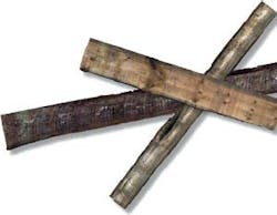
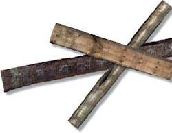
Infected pine trees that are felled and processed for lumber show blue stains in the wood and, in worst cases, exhibit cracks from a lack of moisture. These stains prompted some customers, notably from the Pacific Rim, to reject the wood for building purposes (see Fig. 1). This has created opportunities for mill operators to add color vision capabilities to traditional laser-based scanning technologies for optimization at the edger and trimmer nodes of lumber processing.
To add color vision while improving spatial resolution that better locates the cracks in the wood at the edger station, Canadian mill- equipment supplier Comact turned to LMI Technologies to upgrade the laser-triangulation machine-vision scanners in its DynaVision M24 modules. The result was the addition of the LMI chroma+scan 3300 to the Comact Edger Optimizer system installed at the Lakeland Mills plant in Prince George, BC, Canada.
Busy beavers
Processing beetle-killed logs presents significant challenges because of the reduced moisture content, which causes shrinkage and results in large splits or cracks, according to Yvon Hubert, vice president of optimization and control at Comact. Mills such as the Lakeland facility, which process large quantities of beetle-killed lumber, encounter two problems. First, recovery of infected lumber is lowered because a board will break up and either be thrown away entirely or have to be remanufactured down to a lower size. Board breakage can cause process feed problems, contributing to a reduction in efficiency on the order of 20% to 25%, requiring the mill to reduce line speeds by 20% to 25%. A second issue in processing beetle-killed lumber is the presence of blue stain, which affects the aesthetic appeal of the wood, reducing marketability for certain applications.
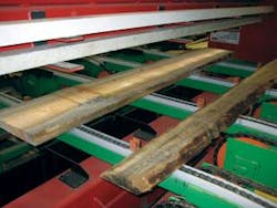
Lakeland Mill inputs 8-ft-long logs through two high-speed end-dogging systems that process 6000 to 7000 logs per shift. The mill overall produces 800,000 bd ft of lumber per day for two shifts. When a log is stripped and turned into an initial piece of rough slab, the edges and ends of the board are still rough, and, thanks to the pine beetle, blue stains or cracks may run along the edges of a 10-in. × 8- or 10-ft-long board. The job of the Edger Optimizer is to inspect the rough slab, find boards with cracks and stains, analyze the cracks and stains to optimize the amount of finished lumber that can be saved from the board, and then removed the defective wood by cutting it away (see Fig. 2).
Removing the cracked wood also reduces the chances of downstream jams when the rough board is turned into finished lumber. “Instead of sending a 2 × 6 board with a crack in the middle, you cut away the 2 × 4 and send the 2 × 2 with the crack to the chipper so you don’t risk clogging the system,” explains Comact’s Hubert.
Through the cracks
After a log is processed into rough slabs, the high-quality center pieces or “cants” go to a fixed gang edger, while the side boards go through the Comact Edger Optimizer with the chroma+scan 3300 scanners. These slabs enter the edger station perpendicular to the conveyor direction to accommodate slabs of varying lengths, depending on what was cut from each log.
Previously, using the DynaVision M24 scanners, the edger only generated a geometric profile without looking at the surface of the board for knots, cracks, blue stains, and other defects. In addition to not being able to “image” the surface of the board, the M24 used dot laser scanning to create 3-D profiles with 1-in. spacing between data points. As cracks from pine beetles become more prevalent, finer cracks needed to be found, so Comact needed a system with much higher resolution.
The new edger system installed at Lakeland Mills replaced the DynaVision M24 systems with 10 chroma+scan 3300 systems (five above and five below the conveyor). By using more cameras with denser spacing of the laser dot projectors, minimum scan resolution was decreased to 0.3 in. while adding the ability to acquire color images of each slab.
A quadrature encoder attached to the Comact edge conveyor tracks conveyor movements, which are then passed to the vision system. As each board passes between the upper and lower rows of chroma+scan 3300 scanners, CMOS imagers collect images of the laser dots projected onto the board’s surface at a rate of 2000 frames/s.
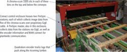
By combining the encoder values for the z axis, and x and y locations for the laser dots in each image, the LMI FireSync Station can generate a complete geometric profile for each board. Laser light for triangulation helps to cut down on the impact of ambient light for precise 3-D data point acquisition. Each scanner has built-in image processors that isolate the laser light in each frame. The displacement of each laser dot from the calibrated norm established during installation in the Comact edger scanner carries with it height information (see Fig. 3).
Controlling the power, data, and synchronization of the chroma+scan 3300 system is an LMI FireSync Master. Each sensor communicates to the Master through a single Ethernet cable. The profile data are passed through the master to a pair of FireSync stations, each of which collects data from five of the chroma+scan 3300 sensors and then combines the images from the sensors into a single image. The FireSync Stations are connected via Gigabit Ethernet (GigE) to the Comact Optimization software, which converts the data from the machine-vision system to instructions for the six saw blades used to trim the slab. An industrial monitor at the end of the Comact Edger Optimizer frame shows the image of the board at the machine, while a FireSync client interface allows the operator to view the FireSync operation from a remote control booth connected to the plant’s network.
One of the benefits of the FireSync platform is that it uses the conductors in the GigE cable to carry power and time synchronization signals, according to Kevin Brown, marketing manager for the wood division at LMI. It is a critical feature in high-speed scanning systems that must synchronize multiple scan heads to ensure accurate 3-D model information in the final, combined image.
In addition to two CMOS triangulation scanning sensors and four laser dot projectors, each chroma+scan 3300 also includes a row of white LEDs and two 640 × 480-pixel color CMOS sensors to acquire an image of the board face as it passes. The system uses multiple sensors to cover a wider area while still generating the laser dot density and high-resolution geometric profile required by the edger application; the same applies to the color imaging CMOS sensors.
“Each color sensor looks directly down and covers about 12 in. of the field of view, which is 24 in. for the 3300,” explains Brown. “Each of the monochrome imagers looks at the lasers from two laser modules. Because of the optical modeling of this sensor and the depth of field and field of view we need to use four images to get both the profile and vision data.”
Image processors built into the 3300 apply intensity thresholds and blob analysis to the surface images of the slab acquired by the color sensors, isolating the blue stains on the board. These data contribute to the “grade” of the finished board. Adding automated color scanning at the edger introduces some of the functions of grading much earlier in the process, producing higher value boards by eliminatingon cracks and potentially other defects such as stains, knots, and pitch, and making a higher-value decision by detecting important defects consistently early in the manufacturing process.
The combination of high-density 3-D differential profiles and color vision helps ensure that surface and dimensional information are precisely matched on the board surface, which eliminates the need for multiple scanners with separate scan frames, and reduces cost and floor-space requirements for implementation while increasing reliability.
The Comat Edger Optimizer scans and processes 60 pieces per minute. Each edger has one variable saw and a bank of five fixed saws. The improved performance of the automated edger is showing some of the limitations of the current edger and so the mill is investigating adding a second variable saw to get more value out of the system.
Guy Jubinville at Lakeland Mills quality control reports that going from 1-in. scan increments to 0.3-in. scan increments enabled better detected edge shape, and increased the mill’s ability to produce #1 grade lumber. Similar chroma+scan systems have been installed in other processing nodes at the mill, including the lumber grader. These automated grading systems provide the consistency and flexibility needed for the rising number of lumber grades going through the mill, which had pushed the limits of manual grading systems.
Going from manual graders to the Comact GradExpert system, for example, resulted in an increase of 12% to 30% for #1 grade lumber; economy grade dropped from 15% down to 6%, and the number of 6- and 7-ft boards produced dropped from 15% to 3%. Guy states that he was very skeptical about the automated grading systems before they were installed and now reports that it is the best decision the mill has made.
null


