Vision-guided robot system trims parts
In a deflashing workcell, camera, lighting, and software combine with four-axis robot to remove excess plastic from injection-molded auto parts.
By Richard Zens
Using a robot to trim flashing from an injection-molded-plastic part is not a new application. However, when the robot is being fed from six different lines, each with different dimensions and features-including some with metal cores inside the plastic-cost-effectively guiding a water-jet cutting tool becomes very challenging. A US automotive-part manufacturer, tired of high labor costs and insufficient quality controls necessitated by flashing removal in a variety of plastic parts, recently turned to Abacus Automation to come up with a flexible robot workcell that could remove the excess material while providing quality inspection.
Injection-molded-plastic parts have a seam where the two halves of the mold come together. Plastic enters the seam during injection, creating excess plastic around the part called flashing. This flashing has to be removed, typically through some cutting mechanism, followed by deburring, which is the grinding away of the last bits of excess plastic to produce a smooth finish. In most cases, this process is done manually, especially in companies with high product mixes that do not easily lend themselves to automation.
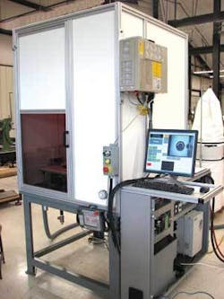
This was the situation that the automotive-part supplier brought to Abacus Automation last year. The client wanted a single robot workcell armed with a Jetech Model 5013 pump system water-jet cutter to deflash products from six production lines, each making its own part. To increase the production line’s flexibility further without adding additional plant networks to pass along product data, the workcell would not know what part was coming down the line. The need for flexiblity was one of the reasons Abacus decided to go with a vision-guided robot workcell for the deflashing operation (see Fig. 1).
The system is based on a compact Opteon B1J “wafer camera” with USB 2.0 output and offset red LED light connected to a standard Dell PC host. Abacus uses MVTech Software’s Halcon image-processing library to locate a ridge feature running around the part perimeter. The data are transferred to a DENSO robot controller via Ethernet, including the ridge centroid location and preferred ridge width based on part model.
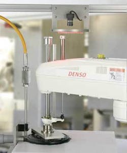
The controller converts the ridge location data to an offset from the robot’s centroid location, determined during an earlier vision-robot calibration step, and guides the robot’s water-jet-cutter end-of-arm tool to remove the flashing from the part. If the ridge location or size do not meet the specifications of the part manufacturer, or a metal insert is not completely covered by the injection-molded plastic, the robot controller passes a signal along to a downstream PLC to reject the part (see Fig. 2).
By mounting the Opteon B1J monochrome CCD camera with red LED ringlight and the water-jet nozzle on the steel supports, Abacus alleviated some of the payload pressures on the robot and improved the camera’s ability to collect an unobstructed image of the ridgeline on top of the part, which is the first step in the deflashing and inspection process. Abacus chose the B1J camera because of its small size, digital high-speed USB 2.0 output, and relatively high-resolution progressive-scan operation (see Fig. 3).
Progressive scanning is required because the user requested at least six parts deflashed per minute, which leaves little time for identification, inspection, and deflashing. Finally, the Opteon cameras have very low noise, which reduces the need for high-resolution sensors even in high-precision manufacturing for edge detection, as well as excellent white balance. Using other cameras, the system requires four to five pixels to find an edge, while the Opteon’s low noise can find an edge between two pixels.
Parts ranging from 6 to 20 in. on a side and between 1 and 4 in. in height are fed to a collecting conveyor upstream from the deflashing station and singulated on a feeding conveyor by a PLC/shuttle located just upstream from the deflashing workcell. A steel worktable, instead of the more common aluminum extrusion support, was constructed on the side of the conveyor to provide additional stability for the DENSO SCARA HM-40852E 4-axis robot, increasing the speed at which the robot could move while maintaining tight positioning accuracy. The combination of heavy end-of-arm tooling with high-speed robot arms and the resulting mass/momentum must be considered when designing a workcell, especially in light of the trend toward larger robots moving faster in a wider variety of manufacturing operations.
Abacus chose the DENSO SCARA HM-40852E robot because of its relatively long 850-mm reach in a small package and familiarity with the product. While many robot workcells are simulated in virtual environments, the company used an existing DENSO robot at Abacus for proof of concept, only simulating the water-jet-cutting operations before moving onto code generation.
Find the Center
Because the plant network does not feed production data to the vision system, which acts as the supervisor to the robot workcell, the workcell does not know the make and model of the part coming down the conveyor. Instead, the vision system must determine what part has entered the workcell and determine the shape of a golden part based on stored data.
The key is a ridgeline on top of the part. While the ridge shape, size, and perimeter length change from part to part, these characteristics can also vary by as much as 3/8 in. This means that while stored-part data can be used to identify the part, the actual ridgeline has to be isolated and the coordinates identified for every point along the ridge to guide the robot to make the best deflash cut. The camera and LED light are mounted slightly off the vertical axis in a known position. In this way, the top of the ridge is the brightest point on the collected image, while the side of the ridge is cast in shadow. Flashing extends from this ridge out to a distance of an inch in some cases, so the ‘shadow’ cannot be used as the sole guide for the robot to position the part under the water-jet cutter.
Instead, the MVTec Halcon image-processing library isolates the ridge using edge detection, locates the centroid of the ridge, and measures the shape and length of the ridge perimeter. Chassis 3.0 software shipped with the Opteon camera provides basic camera controls and interfaces with third-party image-processing libraries without the need for a separate frame grabber.
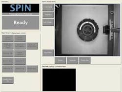
The Opteon camera passes the image data to the Pentium-based Dell PC across a USB 2.0 interface where Halcon image-processing algorithms take over. Abacus created a supervisory program in Visual Basic to call each algorithm in turn and provide a method for the technician to operate the workcell, and change thresholds and other parameters (see Fig. 4). The operator can control separate systems (such as turning the water jet on and off) through the Visual Basic software package. Signals are passed to each subsystem through an optoisolated I/O card in the PC host.
The processed image yields the ridgeline size and shape, which is compared against part data stored in a Microsoft Access database on the PC host hard drive. A match in the product database produces the approved ridge width, and that width along with the centroid location of the ridge around the full perimeter of the part are fed across an Ethernet cable to a nearby DENSO robot controller, operated through a mounted touch screen on the steel housing.
The vision system and robot are calibrated to a single coordinate space during setup and maintenance. This allows the robot controller to create an offset from the robot’s center point for each point along the edge. The robot controller converts the offsets to a series of movements and the robot picks up the part from the conveyor and moves it under the stationary water-jet to deflash the plastic part.
Some of the parts have metal inserts that can protrude through the ridgeline. When the vision system detects shapes indicative of metal protrusions, the part is rejected. The same is true of parts with ridges of less than 1 in. in diameter. In these cases, a signal is sent from the vision system to the robot controller and on to a nearby shuttle to remove the defective part from the conveyor.
Richard “Dixie” Zens is vice president of Abacus Automation, Bennington, VT, USA; www.abacusautomation.com.
Company Info
null


