Machine vision and concurrent processing inspect automotive parts
David Lieberman, Contributing Editor
Polydec is a leading supplier to the global automotive industry, manufacturing tens of millions of micro-axles every month. The company relies on advanced technology and rigorous quality assurance to ensure that these hardened-steel devices, a critical component of automotive step motors, are correctly manufactured. The company achieves what it says is 100% quality assurance as the result of an integrated image-processing system constructed for it by system integrator Ryf and camera vendor Kappa opto-electronics.
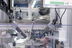
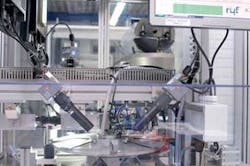
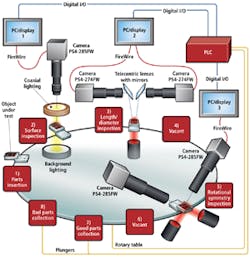
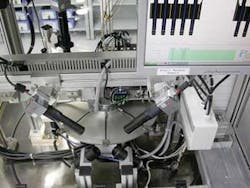
The Polydec micro-axle inspection system is based on a rotary positioning table that sequentially delivers micro-axles to multiple imaging stations that visually inspect different parameters. Each PC-based station consists of a tailored set of camera, lighting, and optics, with each set optimized to measure a particular set of parameters (see Fig. 1).
According to Polydec, the high standards of precision and large production volumes in the automotive industry require constant development of the complex production process to ensure proper mechanics and quality requirements. The company is also a volume producer of automotive shafts, precision test plungers for the electronics industry, and other components for the high-end watch industry and for medical applications.
The eight-position rotary table used in the system is configured with six active stations (see Fig. 2): one for inserting a set of five micro-axles, three for performing inspection tasks, and two for sorting micro-axles after inspection into good and bad parts bins. Each five-axle set travels sequentially, station by station, from Station 1 to the end of the line, which occurs at one of the two collection bins for accepted and rejected parts.
A generic PC and LCD monitor are dedicated to each of the three vision processes. The PCs interface to a Simatic PLC from Siemens Energy and Automation, which physically controls the system. The PCs use simple digital I/O signals to indicate to the PLC, after inspection, which micro-axles are acceptable and which are not.
With a dedicated PC per function and rotary positioning, multiple functions can be carried out concurrently at the various stations, reducing overall inspection time. Polydec, which had previously been using standard video cameras for inspecting micro-axles, said the new system, with its high-resolution cameras, greatly improves speed and accuracy, with the speed benefit coming primarily from inspection concurrency. According to Polydec, the new system needs less than a second to check five workpieces simultaneously.
The micrometer-scale product parameters visually inspected by the system are length, diameter, surface texture, bevel radius, and rotational symmetry (“bending”) of the micro-axles.
Going into action
In operation, a conveyor belt automatically feeds a set of five micro-axles to the Polydec system at Station 1. Here, a proprietary parts-loading system inserts the axles into a bracket assembly at the outer edge of the rotary table. This bracket assembly holds the parts securely in place during the inspection processes with the assistance of a vacuum system.
Station 2 in the Polydec system uses a Kappa PS 4-285 FW camera with an endocentric lens to inspect the position and quality of different textured areas of the micro-axles. For proper operation, the 1–2 mm at the ends of the micro-axles must be smooth and glossy, while the texture of the area in between must be roughened (or “matted”) to a certain degree.
The reason for the texture differences is that the axles, when mounted, will be pivoted on the blank ends, while a plastic wheel will be molded onto the axle during assembly and the rough zone is necessary to guarantee an effective grip of the plastic on the metal.
The camera contains a Sony ICX285AL CCD chip—a 2/3-inch progressive-scan, interline-transfer sensor with microlenses in a 1434 × 1050-pixel format. The CCD’s square pixels measure 6.45 × 6.45 μm, and it has a 63-dB dynamic range and 0.02-lux sensitivity with a 100-ms exposure time. It is equipped with an endocentric lens and uses both coaxial and background lighting.
The Kappa PS 4-285 FW camera is suitable here, as well as at Station 5, because it provides suitable image scale independent of the working distance, as well as excellent sensitivity and signal-to-noise ratio (63 dB).
These cameras provide selectable interfaces: FireWire, Camera Link, and Gigabit Ethernet. All the cameras in the Polydec application use a 400-Mbit/s IEEE 1394a FireWire interface, which provides the link from the cameras to the DirectX9-enabled graphics board in each of their associated PCs.
Station 5, which is responsible for inspecting the rotational symmetry of micro-axles, also makes use of the PS 4-285 FW camera but in a paired configuration with telecentric lighting and telecentric lenses. The two cameras are placed above and on opposite sides of a micro-axle at about a 45° angle.
The benefit of using a pair of cameras at Station 5 is that it allows the system to discern the presence of any bending deformation in the micro-axles without having to actually rotate them during the inspection. Telecentric lenses and lighting are necessary here to avoid perspective distortion from parallax errors.
The remaining image processing station, Station 3, makes use of a pair of Kappa PS 4-274 FW cameras, chosen for their high resolution independent of the working distance. Their task is to measure the length and diameter of the micro-axles, as well as the angle of the bevel at the axle ends. These cameras are based on a Sony ICX274AL CCD chip, which is a 1-1/8-inch, progressive-scan, interline-transfer device with 4.4 × 4.4-μm square pixels in a 1688 × 1248-pixel format. Its dynamic range is 56 dB; sensitivity is 0.05 lux with a 100-ms exposure time.
The Station 3 cameras, mounted on a horizontal plane parallel to and on opposite sides of a micro-axle, have telecentric lenses and utilize telecentric lighting to prevent misreading from parallax errors. A pair of mirrors is also incorporated into the subsystem.
Because of space constraints, the cameras cannot be mounted perpendicular to the micro-axles to provide a direct optical path, so the mirrors are added in order to redirect the image of the parts into the cameras’ field of vision for diameter and bevel angle measurements, while converging the images optically to measure micro-axle length.
Station lighting
Different kinds of lighting are used at different station: both Stations 3 and 5 are lit from below by telecentric lighting, which is adequate for inspecting parameters such as length and diameter. One perpendicular lamp is used in the dual camera/mirror assembly in Station 3; dual 45° angled lamps are used in the dual 45° angled cameras in Station 5. Only the silhouette of the part—a black image on a white background—is important to check size or symmetry.
The lighting at Station 2, like the inspection task performed there, is more complex because a more detailed micro-axle view is required to inspect texture. For Station 2, the color variations are important to determine the intensity of the roughened zone. This is the only station where measurements are in pixels and not in millimeters.
Here the micro-axles under test are illuminated by a circular fluorescent light source, while the inspection area is backlit from below by an array of LEDs. The backlighting serves to brighten up the background and increase the contrast. This arrangement also prevents parasitic light effects from sunlight and other potential sources.
The fluorescent ring lamp is by necessity coaxial with the micro-axles. A light coming from under would show only the shape. If the light met the part straight from above, there would not be any shadow and the dark zones could not be seen and measured, which reveals the intensity of the roughened zone. So the light needs to be in the same axis as the camera.
A ring configuration provided the necessary geometry. Since Polydec wanted to show the three-dimensional appearance of the roughened zone, it needed to light the part at an angle but for the whole perimeter.
If any of the micro-axles fails inspection at any of the stations, no further inspections are carried out on it and the inspection results are saved for statistical analysis. Stations 4 and 6 are vacant.
Image analysis
After all inspections have been completed, small plungers at Stations 7 and 8 are actuated and the vacuum retention released to force the micro-axles into collection receptacles for parts that have passed muster (Station 7) and those that have not (Station 8). Fully loaded with five micro-axles at every station, the inspection system carries a maximum of 40 micro-axles at any one time.
The Polydec application runs under control of Kappa Xero integrated image-processing software and is created with Halcon from MVTec Software. The Xero image processing library provides modules for such functions as integrity checking, particle analysis, luminance distribution, contour measurements, and other common inspection routines. The GUI can display the surfaces of five micro-axles, plus statistics on the strength of the matting in the middle section and the presence or absence of an undesirable brown finish on the glossy ends (see Fig. 3).
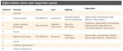
The three imaging stations in the micro-axle inspection system perform some of the same and some different image-processing tasks (see table). All carry out segmentation and morphology, for example, while only Station 2 applies edge detection and blob analysis to its task of performing surface analysis. Both Station 3 and 5 also support more precise subpixel edge detection, as well as 2-D transformations to perform their tasks: respectively, length, diameter, and bevel angle at Station 3 and rotational symmetry at Station 5.
