Laser scanners read dot-peened code
Laser line illumination is effective in difficult-to-scan 3-D Data Matrix code applications.
By Larry Smyth
Peen marking is a common method for identifying parts. As with its less-flexible cousin, stamping, peening creates an impression in the part surface. Peen marking typically uses a single point that is repetitively, precisely located and then driven into the surface to create numbers, letters, artwork, or codes. Peened area codes-specifically peened Data Matrix (DM) 2-D codes-are becoming the standard for tracking information on a vast number of automotive, aerospace, military, and industrial parts. This is because peen coding is inexpensive and durable, and DM encoding technology is powerful enough to both prevent errors and correct damaged codes. Furthermore, area codes can contain far more information than common barcodes.
Unlike alphanumeric character sets, DM codes cannot be read by people. This is bad because it is necessary to use a scanner to read the code; however, this is good, as the scanner output is directly available for electronic processing and storage without any human interpretation and re-entry errors.
Peened area codes typically do not have the high contrast seen in black-on-white barcodes. Scanning peened codes requires artificial means to create the necessary contrast. Fortunately, peening creates a 3-D impression, and structured lighting can be used to create high contrast. For example, appropriate lighting can make the impression look like black dots on a white background, or vice versa. With favorable lighting, the high-contrast code can be readily captured in a CCD or CMOS digital area-array camera for decoding in a PC by appropriate algorithms.
Earlier-generation peened-code scanners only worked reasonably well when various constraints were practiced. Current camera-based scanners work well in most cases, as the digital-camera performance-per-unit price has improved, and more sophisticated algorithms and lower-cost processing have made camera-based scanners increasingly effective. Structured lighting systems have also improved; however, in many cases, lighting remains the Achilles heel of peened-code scanning.
Data Matrix codes peened on the circumference of tubular parts are a particularly tough scanning problem. As the code is not on a flat surface, there is a perspective problem that becomes increasingly significant as the width of the code increases relative to the tubular radius. Furthermore, unlike rectangular parts, round parts are very difficult to ‘clock’-or radially orient-for optimum presentation to the scanner. Then, not only is the code unlikely to be centered in the scanner field of view, but also the further away the code is from the tubular centerline, the further the code is in the scanner depth of focus. Under such conditions it becomes very difficult to develop good contrast through structured lighting, and the resolution of the scanner optics for such a large operating volume is also a serious issue.
Wheel Serialization
A wheel serialization system can be used for traceability, which is a safety requirement of automotive OEMs and the US Department of Transportation. Serialization is particularly valuable for saving money through manufacturing optimization and enhanced product quality. Without a robust automated means of collecting data, production staff cannot be aware of much of the actual manufacturing history of a part.
For example, a wheel plant tracking system we developed consists of a peen-marking and verifying operation, wheel scanning stations throughout the manufacturing process, and a database system (see Fig. 1). The peened DM codes act as rugged identification (ID) tags for tracking since a variety of difficult processes are encountered, including high-temperature heat treatment, abrasive shot blasting, machining, and painting.
By placing the DM code on the exterior diameter of the wheel, automated marking and scanning can be simplified. However, as the rim section of the cast or forged wheel starting shape is then fully machined, the original DM code is removed. Fortunately, by scanning the ID tag as it enters the machining cell, it is practical to remark the wheel rim with the original peened DM code without ambiguity before proceeding to the next manufacturing operations.
While placing the DM code on the wheel circumference can simplify access, there remains the significant problem of aligning the code for automated scanning. This radial orientation, or clocking issue, can be handled by multiple scanners or conversely by multiple DM codes spaced around the circumference. Although several additional peened codes are far less expensive than purchasing additional scanners, this preferred technique is not practical with conventional machine vision. Fortunately, a particular form of structured lighting appears to have great potential for such difficult peened-code scanning, namely laser-line illumination.
Laser Line Illumination
Lasers produce coherent, monochromatic collimated light, which makes them the most structured type of light available. The collimated nature results in very narrow beams, which are not particularly useful for area illumination. On the other hand, a point laser beam can be optically shaped into a line, as can commonly be seen in use for linear barcode scanning. Then, by moving the code or scanner relative to each other, an area illumination is achieved. Alternately, a single point laser can illuminate an area by a raster scan movement in the two area planes. Either way, multiple camera frames are required to capture the full illuminated image.
Why is laser line illumination potentially useful for difficult peened-code scanning? Because the laser illumination is so collimated, there is little to be concerned with in depth-of-focus issues. And since relative motion and multiple images are required to illuminate an area to be scanned, the field of view is optically of far less consequence. However, unlike structured area lighting, line lighting cannot generate artificial contrast, and so another physical phenomenon-optical triangulation-must be used.
Laser Line Profile Scanning
The principle of range measurement based on triangulation is ancient. Today, compact laser CCD displacement sensors based on the same triangulation principle are widely available. Such units only require a point laser, suitable optics, and a linescan CCD sensor to detect the back scattered light. They are available in a broad range of capabilities as far as measurement ranges and reference distances, including high resolution and excellent linearity along with high measuring frequency.
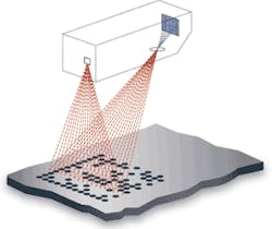
Recently, line laser equivalents have become more common. They are similar to point sensors but project a laser line and capture the backscattered light in a CMOS or CCD area-array sensor. Such high-end sensors can scan thousands of lines per second and multiple measured points per line (see Fig. 2). For example, the high-precision scanCONTROL laser line scanner from Micro-Epsilon Messtechnik measures 256,000 points per second, where the user can increase the linescan density by lowering the linescan rate, or vice versa. While it is also possible to use a high-resolution linescan camera in combination with laser line illumination to achieve much higher data point capture per second, this approach is limited to applications where there is essentially no depth-of-field variation, as in high-speed sheet inspection.
Laser Scanner Trials
Using a LMI Technologies SLS-5035/100 unit, we conducted trials with a point laser displacement sensor focused on a DM peen-coded cast-aluminum surface. The laser beam was roughly centered and aligned with a row of peened impressions as the sample was translated slowly by hand at a fixed stand-off height. It was found that the peened indentations could readily be distinguished from the background surface (see Fig. 3).
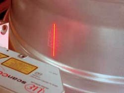
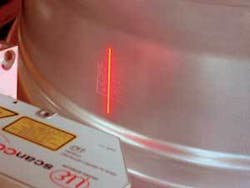
Arrangements were then made to test some DM peen-coded cast-aluminum wheels with a laser line profile sensor mounted on the wheel conveyor system of a commercial wheel QA system. A 20-mm, 14 × 14 matrix format was used, and the codes were peened into the rim exterior circumference. It was then possible to convey by roller the peened codes past a fix-mounted, commercial line scanner (see photo on p. 89). The code radial orientation could readily be changed to test the effect of varying degrees of nonorthogonal alignment within the scanner measurement range. Furthermore, the laser line orientation to the wheel axis and code orientation could also be varied. Peen-coded cast surfaces, machined surfaces, and painted surfaces were all tested at the fixed conveyor speed of approximately 400 mm/s.
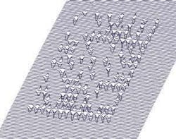
Unlike the previous result, which was the equivalent of a single line scan produced by a point scanner, the linescanner produces sequential line scans. Thus, a 3-D surface map was to be expected (see Fig. 4). Although one cannot simply see the Data Matrix code, one can imagine that the peened code is very likely to be captured once the sequential scans are sorted and the background surface is subtracted. It was then shown that this can readily be accomplished with state-of-the-art algorithms.1
When the radial orientation of the DM code was tested, and we found that the laser linescanner can readily scan the chosen code size on automotive-wheel-size round parts at ±45˚. Thus, by placing four DM codes around the wheel circumference at 90˚ increments, true on-the-fly scanning becomes feasible. Furthermore, by making each of these four codes different and continuously profiling the circumference as the wheel passes, it is even possible to calculate the radial orientation of the round part. For automotive wheels, this is important automated processing information concerning valve- and lug-hole locations.
DM peen-coded identification is becoming the most common means to mark industrial goods and, in particular, items where the code sees some abuse from further processing and use. Camera-based scanners with structured lighting are currently the best technology for machine scanning of these codes. There are, however, some part configurations that are more difficult to scan, and a novel means to use laser line illumination has been shown to be particularly effective.
Unlike structured-light area camera systems, laser triangulation maps the encoded surface. Then, by simply subtracting the general background surface, the DM code can be extracted for decoding. “Simply subtracting” is, of course, an oversimplification of the sophisticated algorithms required to do this feature extraction in near real time. A nearly real-time point-cloud feature-extraction system processed these point clouds.By processing the line-by-line point-cloud output of the scanner, a clean DM array was extracted for decoding.
Work continues on exploring this promising alternative DM scanning technology. While common laser linescanners are rapidly losing ground to area-array-based cameras for linear barcodes, perhaps the future will still see laser line scanning of area codes.
Reference
- C. Teutsch et al., “Evaluation and Correction of Laser-Scanned Point Clouds,” Proc. Videometrics VIII., Electronic Imaging 2005, SPIE (Bellingham, WA, USA).
Larry Smyth is president of B&S Quality Systems, Millersville, MD, USA; [email protected].
null


