INTEGRATION INSIGHTS - Medical Parts Get a Clinical Checkup
Earl Yardley
The inspection of injection-molded medical devices has been a time-consuming operation requiring trained operators to visually check each product for consistency and quality.
During the inspection process for one such device—a central barrel for a drug injection system—each product needed to be examined to ensure that it met a number of strict criteria, after which products could be deemed acceptable for shipment, set aside for recycling, or rejected. Industrial Vision Systems (IVS) has developed a machine-vision system to perform this inspection automatically at a rate of more than 100 parts per minute.
Devices inspected by the system are formed from a black injection-molded shaft and a central recess into which a yellow molded plastic band is affixed. When used, the central barrel moves along a cylindrical tube to expel the drug from the device, while the yellow molded plastic band provides an indication that the correct dosage of the drug has been administered.
Key parameters
To create a machine that was capable of differentiating acceptable products from those that needed to be rejected or reworked, IVS worked with the device manufacturer to determine the key parameters that the manual operators used to inspect the product.
The parameters included determining whether the central area of the injection-molded plastic barrel was free of shorts and flash, the presence of surface defects, and that the yellow band had been correctly affixed around the circumference of the central barrel.
Additionally, each part was examined to guarantee that the sides of the cylindrical barrel were truly parallel. Last, the devices were examined to ensure that no shorts emanated from two molded flanges at the top of the barrel.
The vision-based system replicates this entire handling and inspection process, after which inspected products are sorted into tote bins according to whether they have passed, failed, or need to be reworked.
System design
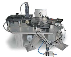
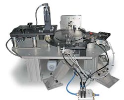
Built from an extruded aluminum framework, the machine incorporates a bowl feeder into which batches of devices are manually loaded. Employing a programmable logic controller (PLC) from Allen Bradley, the pneumatically driven bowl feeder feeds the products onto a linear track that carries them into the inspection station. Once there, they are individually offloaded into recessed areas of a rotary plate.
As the plate rotates, it brings each of the devices under a vision station. After being triggered by an optical proximity sensor that indicates the presence of a product, three cameras—two in the x/y plane and one in the z plane—capture images of the sides and the top simultaneously (see Fig. 1).
Images are transferred via FireWire interface to an industrial PC where they are analyzed using NeuroCheck software from NeuroCheck.
To inspect the body of the product from both front and rear, the two 24-bit color cameras were placed alongside one another in the x/y plane and an optical arrangement of mirrors configured to allow each camera to capture a 180° view of the body of the barrel. Together, they provided a 360° view of the product. The third camera faces downward to capture an image of the head of the barrel.
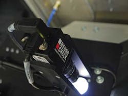
Devices were illuminated from above by a polarized Schott LED ringlight from Moritex USA as they pass through the inspection station. Captured images then show the central portion of the surface of the mold, the complete body, and the top (see Fig. 2).
Imaging algorithms
Machine-vision inspection functions were selected from standard routines available in the NeuroCheck software and deployed to check five images of the part that were captured by the system: the four images taken by the two pairs of horizontal cameras and the one taken from the top.
The primary software operation performed by NeuroCheck on the four side-view images of the product was used to determine whether the yellow band was formed around the entire barrel of the device and that the color of the band was uniform.
Initially, the system was trained to identify acceptable color tolerances within an upper and lower yellow color band. During the inspection process, a color-matching technique can be applied across the bands in each of the four images to determine if the sections of the image are of the correct RGB value and whether the coverage is even. Any disparities indicate that there are dark areas where the yellow band may have been molded incorrectly or that the band is missing entirely.
The check function in the NeuroCheck software takes each RGB image and derives a gray-level image from it. The brightness of every pixel in the derived image provides an indication of the color similarity between the digitized images and similarly processed known reference colors.
Parallel lines
NeuroCheck software also determines the degree of parallelism of the barrel edges. Edge detection is used to identify points in the image where measurements should be taken. From the resulting image, two lines are selected that represent two edges of the barrel. Because the parts sit in a horizontal fashion in the tooling, the locations of these outer edges and a pseudo-baseline are used to calculate the angular offset and thus the parallelism of the lines.
Because the parallelism of the lines is calculated from interpreting the location of individual pixels at the edges of the barrel, the pixel data can also be used to determine whether any shorts or flash are present in the part.
This is performed by using another function within NeuroCheck that computes ideal straight lines from existing regions of interest in an image. The software examines individual pixels in the images of the barrel edges and uses them to compute reference lines where pixels representing the edges should ideally appear.
If shorts or flash are present on the outside of the body, then the edges detected by the software will create a line that will differ from the reference, thereby providing a means of flagging parts that may need to be reworked or rejected.
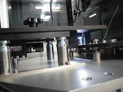
Images taken of the top of the part were also used to check that there were no shorts or flash emanating from two molded flanges at the head of the molded part (see Fig. 3). To do so, the head of the part is first identified from the image using edge detection. Specific regions of interest are then measured and compared with a reference template to determine whether the part is within acceptable tolerances.
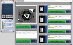
After the software has examined the characteristics of the device, it then determines whether the part meets all the tolerances that have been specified, or whether the part must be reworked or rejected (see Fig. 4).
To sort the individual devices into the appropriate tote bins, the plastic injection-molded part is indexed around the rotary plate from the inspection station until it reaches one of three other stations, where it is removed from the plate using pneumatic actuators and dropped into a tote bin.
The data from the image-processing system can be used to efficiently inspect and categorize the devices, but they also have other benefits. Because it is also possible to collect statistical data during the inspection process, after the machine has checked several batches of product, the data can be used to determine how any changes in acceptable tolerances will affect the yield of the product.
Earl Yardley is director at Industrial Vision Systems (IVS) Ltd. (Kingston Bagpuize, UK).
Company Info
Allen-Bradley, Milwaukee, WI, USA
Industrial Vision Systems Ltd., Kingston Bagpuize, UK
Moritex USA, San Jose, CA, USA
