Vision-guided robots assemble wheel parts
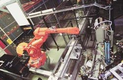
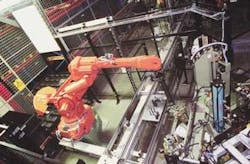
Manual assembly of automotive parts is slow, fatiguing, and often unreliable. To overcome these limitations, the transmission division of Volvo Car Corp. Components AB (Köping, Sweden) shifted from manual assembly to a robot-and-vision-based system that has dramatically boosted the production of front-wheel units for the Volvo S80 (see Fig. 1). Under the direction of the robot-and-vision system, production equipment is assembling 17 wheel components to form a wheel unit within 30 seconds. These wheel units are eventually delivered to the Volvo car factory in Göteborg, Sweden.
FIGURE 1. Robot and vision system for assembling and inspecting Volvo car wheels incorporates monochrome digital cameras and geometric pattern-recognition software. It integrates robots, a pallet-and-conveyor system, programmable logic devices, personal computers, a server, an Ethernet TCP/IP network, a Profibus network, and multiple electronics units. Under the direction of the robot-and-vision system, production equipment can assemble 17 wheel components to form a complete car wheel unit in 30 seconds.
Systems-integrator ABB Industries/Powertrain (Vasteras, Sweden) developed and installed the wheel assembly line. It purchased the vision system used in the Volvo line as a finished subassembly from CVR Vision Control AB (Stockholm, Sweden); CVR has since been acquired by Orbis Corp. (Oconomowoc, WI). Mats Johansson, vice president for the automotive industry at ABB Industries, says Volvo Köping selected his company in a competition, based in part on ABB's previous conveyor-and-robot experience in delivering gearbox assembly systems to the car manufacturer.
The new vision system uses the Cognex Corp. (Natick, MA) MVS-8100 PCI frame grabber and PatMax geometric pattern-recognition software and Sony Electronics (Park Ridge, NJ) XY75 black-and-white digital cameras, which deliver VGA resolution, 10 frames/s, and a serial RS-232 output that supplies movement coordinates to the ABB robots. It is a critical element in the multi-work-cell wheel production line, which ABB has meshed with robots and a pallet-and-conveyor system. Pattern-recognition software enables the robots to find and select the proper wheel components at each assembly work cell from a shipping container located below the cameras. The integrated vision-guided robot hardware and software system has resulted in boosted wheel-production rates and fewer assembly errors.
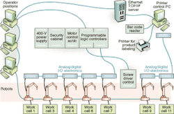
FIGURE 2. Overall wheel-assembly line at the Volvo Köping factory runs over Ethernet: TCP/IP communications (green lines) and link three system PCs (left) with the server (top right), as well as the robot-and-vision work cells. Profibus communications (broken blue lines) connect one of the two PLCs with the robot-and-vision units. At each work cell, electronics units (blue boxes) convert analog signals to digital Profibus signals to drive work cell operation. Another PC (far right) controls both the bar code reader and the bar code label printer. Bar code labels are affixed to each steel pallet loaded with finished wheel assemblies. Cells 9 and 11 are not used in this wheel-assembly operation.
The assembly lines are controlled by programmable logic devices (PLCs) from Siemens Energy & Automation Inc. (Alpharetta, GA). They also include a supervisory computer from Prevas Systems AB (Stockholm, Sweden), three IBM Corp. (White Plains, NY) PCs, and an IBM server. The PCs and server are connected over an Ethernet TCP/IP network; the PLCs and assembly cells communicate over a Profibus network (see Fig. 2). Profibus and Profinet are communication technologies sponsored by Profibus International (Karlsruhe, Germany) to promote transparent networking for automation processes.
Other elements in the assembly line include a company robot design in each work cell, conveyors from Bosch Rexroth Star Linjar Teknik AB (Helsingborg, Sweden), and an automated screwdriver unit from Atlas Copco AB (Stockholm, Sweden). ABB set up a complete assembly line on its own premises, where the equipment was tested and approved before installation at Volvo Köping.
Pattern recognition
The PatMax software enables the vision system to recognize the shape of an object after that object's image is captured and stored, even if the object has changed position or if its distance from the robot is longer or shorter compared with the reference image. It recognizes an object by dividing it into geometric shapes and measuring its shape, dimension, and angles. For example, a square object is seen as four lines that have a particular spatial relationship to each other. This relationship is constant even if the object has changed position.
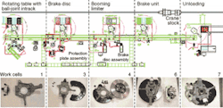
FIGURE 3. Front-wheel assembly for Volvo car wheels progresses from left to right (triple horizontal green lines). The spindle and ball-joint wheel components are joined at work-cell 1 (left). The vision system instructs the robot where to pick up the spindle from one of the containers (black objects along the green line above the conveyor). Subsequent containers are colored differently to show that the robot is picking from a lower level in the container. Two containers are shown because the production line assembles both left- and right-side wheel units, but only one type of wheel unit is assembled in each pass through the line. Subsequent components are added at each work cell. The finished wheel units are each given a barcode and then placed on pallets by the fifth robot (right).
In Volvo's application, five robots work in a 5 × 50-m area (see Fig. 3). They are coupled to automatic-handling machinery to pick up and assemble the 17 components comprising a complete front-wheel unit for both right- and left-side wheels. The components come directly from the suppliers' special packages, which are multilayer box-like containers that are positioned at each work cell. However, the components are not placed in predetermined positions. This setup means that the robots must be able to distinguish between left- and right-hand components, depending on whether right- or left-side wheels have been selected for a given assembly run by the production-control computer operator.
"Each vision system is controlled by a personal computer," says Anders Boman, a Volvo project manager. "The computer-based network ensures that the work cells included in the front-wheel assembly system can communicate with each other and that an operator can monitor the process."
Communications among all units in the production line are essential for accurate stored imaging information depicting the components to be assembled. Each component in a wheel assembly is first photographed. Then, its image is stored so that the vision system can make accurate comparisons when a robot selects a new component from the shipping container located at each work cell. This information controls how the robots pick and turn the components before placing them into a wheel unit.
"The Cognex vision system precisely locates and measures the components to be assembled. This task is accomplished even if the components are in different positions compared to their stored images or if they are located at a lower level [in the container], which makes them look smaller than their stored images," Boman says. "This is difficult to do in other vision systems, in which the object must be in the same position as the reference image to be recognized."
Apparent changes in position and size occur because the components are stored and positioned on different levels of the multilayer containers. These levels have a horizontal separator between them, which is removed by a robot after all the components have been picked from that layer.
Calibrating images
Before assembly begins and after the component images have been captured and stored, coordinate and angle data are added to the images to form reference bases. For example, the operator must enter information defining the height of the uppermost component level in each shipping container. The height information can be changed in two ways—via a height-seeking function using the distance the robot travels to reach that level or using a height-seeking function built into the vision system.
Using these calibrated images and data, the vision system makes comparisons between the images taken of the components about to be picked from a container and their stored images. Deviations from the stored data are calculated by a PC. They become the input data to drive the robots' movements to select the correct component and for the robots to correctly rotate the part for placement in a wheel assembly as the assemblies move along the conveyor on steel plate-like pallets.
Each robot is connected to four digital black-and-white cameras positioned above the containers. Two cameras photograph the left-side wheel components, which are carried in one of the two containers stationed at a cell. The other two cameras capture images of the right-side wheel components, which are stored in the second container. Proper components are picked by the robot from a container and placed in the wheel units that move on pallets placed on the conveyor, depending on whether the production run is assembling right- or left-side wheels.
Assembly starts when the first robot picks a steering knuckle component from a container. If the robot needs a steering knuckle for a right-side wheel, both right-hand cameras take images of the steering knuckle. The images are then stored in PC memory for comparisons with reference images. The comparisons give information about how the desired steering knuckle is oriented in the container and controls how the robot is directed to grasp, turn, and place the steering knuckle.
Eleven work cells are available, but only five are used to assemble the S80 front-wheel units. Each of the five cells contains a collocated vision system to identify the part to be picked from a container. The conveyor carries the steel pallets on which the wheel assemblies are transported.
During the assembly process, a ball-joint component is picked by a robot from the turntable at the rotating table cell. An operator can view identical images on any of three PC monitors positioned along the conveyor to track production. The operator can also manually control the assembly flow, if necessary, because each PC's Visual Basic software uses the same commands.
Parts are progressively assembled at each of the five work cells (see Fig. 3). Box-like containers loaded with wheel components are placed in each work cell from which the robot selects part to be assembled. Work-cell 1 joins the spindle and ball-joint components. The vision system instructs the robot where to pick up the spindle from one of the containers. Subsequent containers are colored differently to show that the robot is picking from a lower level in the container. Two containers are needed because the production line assembles both left- and right-side wheel units. However, only one type of wheel unit is assembled in each pass through the line, depending on which side has been programmed by the production-control computer.
In work-cell 3, a protection plate is added to the spindle of the wheel unit. A brake disc assembly is picked from the container by the robot at work-cell 4 and is added to the spindle. Next, a booming limiter is added at this cell. A brake rotor is the next component assembled at work-cell 6, finishing the wheel assembly.
The finished wheel units are each marked with a barcode and then placed on empty pallets by the robot in work-cell 7 prior to shipment to Volvo Göteborg. Barcoding enables the production tracing of each wheel assembly, which is necessary because of demanding European Union quality requirements. Barcoding also helps to provide a dependable and accurate logistics system for the Volvo Köping factory.
Lawrence J. Curran, Contributing Editor
Company Information
ABB Industries/Powertrain
Vasteras, Sweden
www.abb.se
Atlas Copco AB
Stockholm, Sweden
randburg.com/sw/atlascop.html
Bosch Rexroth Star Linjar Teknik AB
Helsingborg, Sweden
www.boschrexroth.se
Cognex Corp.
Natick, MA
www.cognex.com
IBM Corp.
White Plains, NY
www.ibm.com
Orbis Corp.
Oconomowoc, WI
www.orbiscorporation.com
Prevas Systems AB
Stockholm, Sweden
www.prevas.se
Profibus International
Karlsruhe Germany
www.profibus.com
Siemens Energy & Automation Inc.
Alpharetta, GA
www.sea.siemens.com
Sony Electronics Inc.
Park Ridge, NJ
www.sony.com/videocameras
Volvo Car Corp. AB
Köping, Sweden
www.volvocars.se


