Digital mammography detects early cancer

CCD-based digital mammography imaging system incorporates a novel phosphor converter to resolve small, high-contrast microcalcifications.
By Andrew Wilson,Editor
This year more than 200,000 women in the United States will be diagnosed with breast cancer, and nearly 50,000 will die from the disease. Among women of all ages, breast cancer is second only to lung cancer as the leading cause of cancer deaths. Indeed, breast cancer is the leading cause of cancer deaths of women under age 54.

Fortunately, digital mammograms can now detect cancer at its earliest stages, up to two years before any lump in the breast can be felt. When tumors are found at this early stage, the survival rate approaches 100%. If the cancer has been allowed to spread outside of the breast, however, the survival rate drops to 73%.
Currently, most mammograms are film-based, and radiologists diagnose the developed images on a light box. Although this technology has been successful, it is not precise. In fact, it misses approximately 20% of breast cancers. This detection rate drops further with younger women due to the difficulty in recording tumors in denser breast tissue. As a result, research groups have responded to the demands of developing digital mammography systems with higher tumor-detection accuracy.
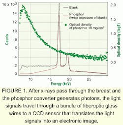
In digital mammography systems, photographic film is replaced with solid-state sensors. In these systems, x-rays are passed through the breast and are converted to photons by a phosphor converter. Next, these light signals travel through a bundle of fiberoptic glass wires to impact a charge-coupled-device (CCD) sensor that translates the light signals into an electronic image that is then digitized and displayed for viewing and analysis. This procedure enables earlier detection of breast cancers than previously possible.
CCD-based sensors
At the Rosenstiel Basic Medical Sciences Research Center of Brandeis University (Waltham, MA), Marty Stanton and his colleagues Walter Phillips and Charles Ingersol, and Alex Stewart at the Detector Development Group have designed and constructed a digital mammography system using CCD devices. During operation, x-rays are first converted to photons by a 27 x 18-cm phosphor screen that is coated with a film of 18-mg/cm2-density terbium-doped Gd2O2S deposited on an aluminized Mylar backing. The absorption of this screen averages 60% in the mammography spectral range (see Fig. 1).
The transfer of light from the phosphor screen to the CCD sensors requires coupling the phosphor screen to a demagnifying fiberoptic taper (Incom; Southbridge, MA), which acts as a lens and focuses the phosphorescence generated by the x-rays onto a 9.5 x 9.5-cm optical surface used by the CCD sensor array (see Fig. 2). With a demagnification ratio of 3.3:1, the taper transmits approximately 6% of the incident photons. "Although using a smaller demagnification taper would have increased the transmission efficiency and modulation transfer function (MTF), it would have required using a larger number of modules to cover the full-field image," says Stanton.
After transmission through the taper, the light signals are coupled to the CCD sensor through a 3- to 5-µm-thick layer of optical epoxy. To design the image detector, Stanton developed a 3 x 2 image array using a front-illuminated THX 7899 CCD from Thomson Components and Tubes (Totowa, NJ). With each sensor comprising 2048 x 2048 imaging pixels, each of which is 14 µm square, the effective pixel size at the imaging plane is 46 µm. "Using careful machining and alignment, the space between modules is less than one pixel (50 µm), so there are no missing data, only some pixels with decreased efficiency," Stanton explains.
To reduce dark current buildup, the detector is operated in multipinned-phase mode. Antiblooming prevents signal overflow from bright regions outside of the breast area from degrading information inside the breast. The full CCD image is read out in approximately 6 s.
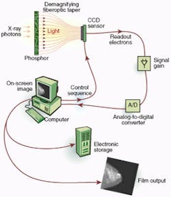
FIGURE 2. In digital mammography system, x-rays are converted to photons by a phosphor screen that is coated by a film of 18-mg/cm2-density terbium-doped Gd2O2S deposited on an aluminized Mylar backing. The absorption of this screen averages 60% in the mammography spectral range.
The Thomson CCD provides an effective dynamic range of more than 20,000, and detector response is linear over nearly all of the full dynamic range. Linearity is important in this application because it allows the measurement of high-contrast tissue and enables corrections for spatial nonuniformity in the system.
"While antiblooming decreases the full-well capacity, it does not affect the signal levels through the breast tissue, which are generally reduced by approximately a factor of 10 from the entrance exposure levels due to absorption and scattering. With antiblooming, the dynamic range is 15,000," Stanton says.
Another goal of digital mammography is high spatial resolution. Ultimate resolution is determined by the effective pixel size of the detector. For the 50-µm-pixel size in the Brandeis University system, the spatial-frequency response of the system begins to roll off significantly below 10 lp/mm. Spatial-frequency dependence of the system response is given by the MTF. For mammography, where low-contrast features need to be resolved near bright features as well as sub-hundred-micron features, both the low- and high-frequency regions of the MTF are important.
While the MTF describes the system's ability to resolve small features, the system's signal-to-noise ratio (S/N) helps to detect low-contrast differences in the image. For finding microcalcifications that are small, high-contrast features, good high-frequency MTF is necessary. However, for identifying tissue masses whose absorption cross section is nearly the same as glandular tissue, a high S/N is important. To see a mass whose contrast differs by only 1% from the background level, a S/N of better than 100:1 is necessary.
Reading data
To read data from the CCD array, Stanton built a custom board in conjunction with Aviex Electronics (Naperville, IL) that both controls data flow from the CCDs and digitizes the output data. Module operation is directed by a 200-MHz Pentium-based host PC using a PCI-based, DIO-32HS, 32-bit, parallel digital I/O interface board from National Instruments (Austin, TX). This board performs single-point I/O and data transfer using a range of handshaking protocols at speeds to 76 Mbyte/s.
After the image is recorded on disk, the image artifacts introduced by the imaging system must be compensated. "To compensate for system nonuniformity, a dark (no x-ray background) image is subtracted from the image," says Stanton. "After image subtraction, the resulting image is corrected for the nonuniform response of the phosphor, fiberoptics taper, and CCD. The final image is then corrected for geometric distortions introduced by the fiberoptics," he adds. On the 200-MHz PC, these corrections take approximately 2 s per image.
To evaluate the performance of the digital system, Stanton and his colleagues replaced the film cassette on a standard Lorad Mark III breast-imaging system from Trex (Danbury, CT) with their digital detector. To evaluate the imaging system, a standard mammography phantom was used, as described by the American College of Radiology (Reston, VA).
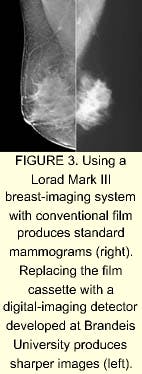
This phantom, currently available from Gammex RMI (Middleton, WI) and Nuclear Associates (Carle Place, NY), simulates a 4.5-cm compressed breast that is composed of 50% fatty tissue and 50% glandular tissue. It primarily consists of a thick acrylic block and a thin, pink wax insert that contains six nylon fibers, five groups of aluminum oxide specks, and five masses. These objects range in size from visible to nearly invisible on a radiograph. Using a mean energy of 17 keV, the Trex system was used to produce images in conjuction with Mark Williams at the University of Virginia (Charlottesville, VA; see Fig. 3).
Digital mammography will greatly improve the ability to find cancer in the dense breast tissue of young women. As well, computer imaging and artificial-intelligence techniques promise to help minimize any errors that radiologists may make.
Because of the increased sensitivity and lower noise of digital systems, medical personnel estimate that patient x-ray dosage can be reduced by 20% to 80%. In addition, wide exposure range and digital image manipulation should reduce the requirement for additional images and result in a further reduction of patient dosage. In traditional mammography, film processing takes several minutes. In digital mammography, images appear in a few seconds. Digital techniques also shorten the time needed to perform examinations and diagnoses.
The JPEG 2000 transform performs a wavelet transform and creates a bitstream of several independent layers that can be given different priorities during transmission to achieve differing image build-up features. Because output coefficients are quantized, the process can be controlled to provide differing compression rates and, therefore, differing output file sizes. Last, the delivered bitstream is entropy coded.
Company InformationAmerican College of RadiologyReston, VA 20191Web: www.acr.orgAviex Electronics
Naperville, IL 60565
Rosenstiel Basic Medical Sciences Research Center
Waltham, MA 02454
Web: www.rose.brandeis. edu/users/detector
Gammex RMI
Middleton, WI 53562
Web: www.gammex.com
Incom
Southbridge, MA 01550
Web: www.incomusa.com
National Instruments
Austin, TX 78759
Web: www.ni.com
Nuclear Associates
Carle Place, NY 11514
Web: www.nucl.com
Thomson Components and Tubes
Totowa, NJ 07511
Web: www.tte.thomson-csf.com
Trex Medical
Danbury, CT 06810
Web: www.trexmedical.com