X-ray technology machine vision and inspect air-bag inflators
X-ray technology machine vision and inspect air-bag inflators
The final nondestructive- test inspection of sealed automobile air-bag inflators by an integrated x-ray/machine-vision system verifies a critical manufacturing process.
By David A. Wilson
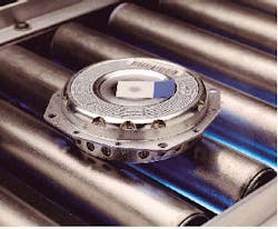
To ensure that assembled air-bag inflators properly expand their associated air bags at the correct rate upon deployment, manufacturers such as Autoliv Automotive Safety Products Inc. (Ogden, UT) are using integrated x-ray and machine-vision systems. These systems are being used in the final nondestructive-test inspection of sealed inflator canisters to verify the number, amount, positioning, and packaging of their installed components. This inspection process therefore guarantees that each inflator has been quality checked after a meticulous manufacturing process.
Driver- and passenger-side air-bag inflators are crucial safety components of today`s automobiles. Comprised of a pyrotechnic material, gas, and support components, these inflator canisters are installed into the steering wheel, dashboard, and side panels of major American and foreign automobiles. Because each inflator component plays an important role during deployment of the air bag upon impact, the sealed inflator canister must be examined prior to installation for correct assembly and packaging to ensure that the air bag inflates properly and protects the automobile occupants from injury.
Since Autoliv began manufacturing automobile air-bag inflators in 1980, the company has been faced with numerous new challenges for meeting the increased demands of automobile manufacturers to produce a wider variety of air-bag products at increasingly higher quality standards, but at lower costs. To meet these needs, the company decided to replace its existing nondestructive-testing machine with combined x-ray and machine-vision inspection systems that would offer greater test flexibility, higher capability, and reduced operational costs.
Important selection criteria for the new inspection system included must-pass radiation safety, performance, and reliability requirements; able-to-test multiple product types; perform all testing within six seconds or less; be operational within a 120-day development cycle; provide powerful image-processing tools; and be integrated into Autoliv`s control, network, and database systems.
After carefully investigating several machine-vision integration companies, Autoliv teamed up its internal machine-build group with Acuity Imaging (Nashua, NH) to develop the desired inspection system. This inspection system obtains an x-ray image of the components assembled inside every sealed canister and then uses machine-vision technology to examine the image for proper component installation.
Dual technologies
The selected inspection system comprises a combination of x-ray and machine-vision technologies. It is set up to detect the presence or absence and positioning of all components sealed within the inflator canister and to gauge the volume of important components.
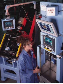
Designed as a manually operated workstation on its inflator assembly line, the x-ray/machine-vision inspection system developed by Autoliv uses a 160-kV x-ray generator from Gulmay Ltd. (Shepperton, Middlesex, England) and a single-field 9-in. image intensifier from Toshiba America Inc. (New York, NY). The image intensifier converts the x-rays to digital images for scanning by the Powervision machine-vision system from Acuity (see Fig. 1 on p. 28).
This machine-vision system contains a 120-MHz, 601 PowerPC vision processor, 24 Mbytes of RAM, a 1.2-Gbyte hard drive, two high-speed DMA serial ports, an 8-bit digital input/output, and two Ethernet ports. Twenty of these machine-vision systems are operating on Autoliv`s production lines.
Several machine controls track each inflator assembly as it passes through the inspection process. They include a 9030 programmable logic controller (PLC) from GE Fanuc Automation (Charlottesville, VA), a programmable coprocessor module for RS-232 communications, a communications coprocessor for Ethernet communications, a BL-501H barcode scanner from Keyence (Saddle Brook, NJ), and several sensors and actuator switches from Netwise Control systems (North Ogden, UT).
To prepare the canister for x-ray test, the assembled and sealed air-bag inflators are placed into a test-fixture loading mechanism--which differs for driver-side and passenger-side inflators--adjacent to the x-ray cabinet. When reflective sensors detect the presence of the inflator canister, a serial communications link is activated between the PLC and the barcode scanner. The scanner reads the inflator`s 10- to 20-character barcode, and the result is temporarily stored in PLC memory before being sent with other test data over an Ethernet connection to Autoliv`s manufacturing traceability system (MTS).
Upon successful barcode reading, a pneumatically controlled slide or index table exactly positions the inflator inside the x-ray cabinet between the x-ray generator and the image intensifier. After the inflator is determined to be in the correct position, the PLC sets interlock switches inside the cabinet to ensure that the inspection system is safely secured for x-ray and imaging-processing operations.
The geometric relationship among the image intensifier, inflator, and x-ray generator determines the magnification of the obtained image. These distances are all adjustable from inside the x-ray cabinet, accommodating a range of inflator sizes. Because some products include denser materials, different x-ray radiation energies are used.
After inflator placement within the x-ray cabinet, reflective and through-beam sensors detect the presence and position of the inflator and trigger the programmable logic controller. The PLC checks all the cabinet sensors and interlocks for proper x-ray radiation safety checks.
When the safety setup is verified, a pneumatic lead shutter is opened. Then, the x-ray generator is energized and passes a radiation beam through the inflator under test onto the image intensifier. A CCD camera system, built into the image intensifier, digitizes the light images of the inflator`s contents. These digital images, in turn, are transferred to the Powervision system for image processing. The varying densities of the components inside the inflator canister determine the different amounts of light collected by the CCD camera. Lead masking is placed around the inflator to reduce image flare; copper plates are positioned along the less dense areas of the inflator to increase image contrast.
Image inspection
After a short delay, the programmable logic controller delivers the serial number and the position of the inflator to the Powervision system. This machine-vision system uses the information to determine which set of imaging tests to perform. It then performs the 10 to 12 prescribed component-presence and volume inspection tests on the inflator image.
These image-processing operations include edge detection to determine that the internal wires are correctly spaced within the inflator, morphological operators to clarify that the shapes of all the various components in the inflator are correct, and gray-scale histogram equalization, which provides density measurements for checking the volume of powder materials in the canister. While the slide or index table repositions the inflator for the next image to be acquired, the previous image is stored as a TIFF file on a SCSI-controlled 2.6-Gbyte optical drive.
After all the inflator inspection tests are completed, the results are sent to the PLC via the serial link for analysis. If the inflator passes all the inspection criteria, the lead shutter is closed, and the inflator is delivered outside the cabinet. Simultaneously, the pass-status lamps are turned on. If the inflator fails any test, a pneumatic lock actuates and prevents the inflator from being moved from its test position.
The data-collection system uses Database Software from Oracle (Redwood, CA) running on a Windows NT server, a test/development Power vision system and monitor, and an Ethernet communications network that is connected to all 20 Powervision systems on the production floor.
Networked testing
At the end of each inspection cycle, the programmable logic controller establishes an Ethernet connection with the Autoliv manufacturing traceability system and transmits the inflator`s serial number, the time and date of test, and all the test results. After the x-ray/vision tests, some leakage, electrical, and force testing are performed by other assembly-line workstations. Inflators that have passed all the test workstations are then queued for packing and shipping.
Before packing, a test operator scans the serial number of the inflator with a barcode reader, and the MTS database is queried to verify that the inflator has passed all the workstation tests. Any inflator that has failed any test or is missing data is not packed.
Recently, Autoliv`s production requirements changed due to new product developments. Because the new production equipment runs faster than previous equipment, final inflator inspection must now be accomplished 1.5 times faster. Consequently, Autoliv is designing an image buffer for the temporary storage of as many as four inflator images. These images will be permanently stored on an optical disk drive while the next inflator is being loaded and positioned for inspection.
By selecting this turnkey x-ray/machine-vision system, Autoliv was able to focus on other aspects of system development, especially as they relate to production and manufacturing. Acuity`s Powervision system met this criterion along with giving Autoliv the ability to make changes to the system`s image-processing software and to save system engineering costs.
Software tools
To program the Powervision system for the required test functions, Autoliv developers used Acuity`s Image Analyst software. As a menu-driven, point-and-click inspection tool, this software provides a library of vision algorithms. System developers can create comprehensive inspection sequences with these algorithms, without programming, via the graphical user interface (see Fig. 2).
Also providing built-in reconfigurable digital input/output triggering, Image Analyst can be set up quickly and deployed on the factory floor for floor inspections, parts rejection rules, and results reporting in real time. For example, a pattern-matching capability detects patterns despite light changes for verifying component placement.
Moreover, Image Analyst presents system programmers with access to its source code. Equipped with this code, programmers can incorporate custom user interfaces, special measurement types, and complex data handling routines. In this manner, programmers can change the software to meet specific machine-vision application needs.
During the development of the air-bag inflator, Autoliv programmers used the Image Analyst code to tailor the operation of the inspection system. For example, the Powervision machine-vision system was normally triggered by discrete, definable optoisolated inputs. However, during system development, programmers added a serial communication link so that the inflator serial number and position information could be used by the machine-vision system to trigger image testing.
DAVID A. WILSON is senior controls engineer at Autoliv Automotive Safety Products Inc. (Ogden, UT).
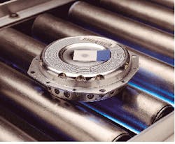
To inspect air-bag inflators (inset), engineers at Autoliv developed an x-ray system coupled to a machine-vision system. In operation, this system combination can detect whether the correct amount of materials have been assembled inside the inflator and whether all the components are present.
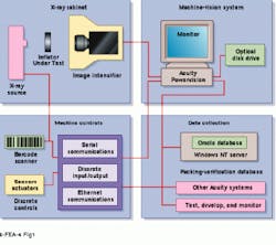
FIGURE 1. Programmable logic controllers, machine controls, and an Ethernet backbone are used to link the x-ray cabinet, machine-vision system, and data-collection equipment to Autoliv`s manufacturing traceability system. By networking these devices, parts tracking and verification have been automated.
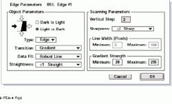
FIGURE 2. Configuring Acuity Imaging`s Powervision system is performed through a graphical user interface that provides dialog boxes for developing various image-processing tests such as edge parameters. As a result, the developer can set or modify scan direction and polarity, gradient strength, and line width, among others, before configuring the system.