Automated Meat Processing
Embedded 3-D machine-vision system guides robotic cutting of beef carcasses
The job of meat processing demands that workers wield heavy cutting equipment in difficult environments during long shifts. One study by David Caple & Associates suggests that 50% of all work-related injuries in meat processing are due to repetitive manual operations.
Seeking to offer a better and safer solution for various meat-processing operations, Jarvis Products took on one of the most challenging vision-system applications, visual servoing—using vision to guide a robot to a moving target so that an industrial operation can be accurately performed. Speed and robustness were essential to all the components, according to Dan Driscoll, automation engineering manager of Jarvis.
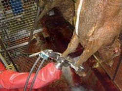
Jarvis developed the JR-50 robot for hock, or hoof, cutting based on a manual Jarvis 30CL cutter mounted on a Motoman six-axis robotic arm guided by a TYZX DeepSea G2 embedded vision system for real-time 3-D machine-vision robotic guidance. Hock cutting happens in the early stages of meat processing. A beef carcass is hung from a chain-driven suspended hook when it enters the hock-cutting station. Typically, a worker wielding a 30-lb 30CL hydraulic- or pneumatic-assisted hock cutter snips the hocks from the carcass before it moves on.
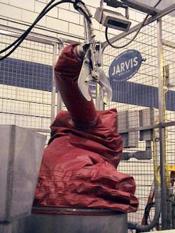
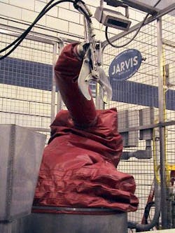
Designed to cut through bone and survive daily washdowns, the 30CL is a heavy, counter-weighted stainless-steel scissor cutter that can tire a strong man during an eight-hour shift. With the combination of a proprietary high-refresh-rate robot controller and high-speed 3-D vision guidance, the automated system for removing the hock from the beef has been accurately performed thousands of times at a major US meat-processing plant since late 2007 (see Fig. 1).
To cut down on worker fatigue while improving safety and repeatability, Jarvis decided to mount the 30CL on the end of a Motoman 50-kg, six-axis robotic arm. “With the tool and associated hydraulic lines, we could get away with a 50-kg robot, but we had to develop our own robot controller. At the time, Motoman didn’t supply a controller that could update the trajectory as often as we needed to find a moving target,” explains Driscoll.
Fast frame rates and the use of 3-D rather than 2-D image data were critical design parameters for the vision system. As the hock-cutting process begins, the carcasses pass between two rub bars, which help to stabilize the swinging carcass. Driscoll added mechanical limits to the robot enclosure to further limit movement, but periodic starting and stopping of the line for upstream and downstream operations guaranteed that carcasses would swing. The vision system would have to be truly real-time 3-D vision. “We tried it with a 2-D vision system, but realized we had further to go,” Driscoll adds.
Better than real time
The vision system has to perform better than the robot’s tolerances if the system was going to succeed. “We selected the TYZX vision system because of the 50-frame/s rate,” Driscoll says. “We’re not there yet, but we hope to be, and that will allow us to update the robot at 50 Hz. We continuously modify the robot’s trajectory all the way until the cutter is ready to go. That’s what you have to do if you want to try to hit a moving target.”
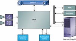
Location coordinates for each hock in the field of view, which can include several animals at a time, are fed to the Jarvis controller over the Ethernet from the TYZX G2. The G2 is a stereo vision system that includes two Micron Technology 752 × 480-pixel CMOS sensors in a factory-calibrated enclosure to maintain the spacing required for accurate 3-D triangulation. It includes an AMCC 440GX PowerPC-based computer running an embedded Linux operating system, a Xilinx FPGA, and the TYZX DeepSea G2 application-specific integrated circuit and sufficient memory to support each chipset (see Fig. 2).
With the TYZX G2 embedded vision system the image analysis and object tracking are performed on the sensor platform. Only the hock-location data are sent to the robot controller system.
“There are two reasons why you want to do 3-D calculations as close to the sensor as possible,” explains TYZX vice president of advanced development Gaile Gordon. “Raw 3-D and intensity data sets can be large, requiring a lot of network bandwidth to send to other components of the system. We believe it’s important to digest that data and process as much as possible right at the sensor where the richest data are available. Also, doing the image analysis on the sensor platform distributes the processing and makes the other CPUs in the system, such as the robot controller, available for other tasks.
“TYZX systems are designed to produce not just the raw 3-D data, but additional higher-level data representations that help reduce computation required for object segmentation and tracking,” he continues. “This enables even an embedded CPU to be able to perform a whole analysis application like hock tracking.”
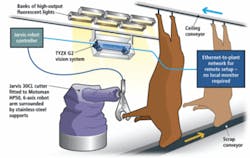
The G2 is mounted slightly upstream from the carcass on the same side of the overhead conveyor as the 30CL-armed robot. As each product is fed into the hock-cutting workcell, it passes through the rub bars and is in motion when the G2 begins to get images from both of its CMOS imagers (see Fig. 3). “We prefer the Micron TrueSNAP global shutter rather than a rolling shutter,” explains Gordon. “Otherwise, the object could move between the beginning and end of the readout cycle, which could reduce the accuracy of the 3-D coordinates.
Parallel 3-D processing
The left and right images are fed into the FPGA for rectification. The rectified data are fed into the G2 chip, which uses parallel processing to perform stereo correlation, searching each pixel for its match in the other image. Metric distance to a point in the scene is a function of the parallax or shift in its location between the two images. TYZX developed a detection-and-tracking demo application based on the Jarvis application requirements. “TYZX sent us a basic program, and we tweaked it from there,” explains Driscoll.
Based on the stereo correlation data, the G2 chip establishes a z distance from the camera to each pixel in the correlated image. Pixels with range data considered outside the cutter’s envelop are discarded, and only pixels within the specified range are considered for final image processing. Once regions within the operating range of the cutter are determined, the system locates and tracks potential hocks based on their size and shape. The x, y, and z coordinates of each hock are sent to the robot controller, which updates the robot arm path as it moves the cutter to the hock. The 30CL design, with a wide opening between the scissor blades, accommodates some misalignment between robot and hock, increasing overall system robustness (see Fig. 4).
“The system has proven itself capable of cutting the hock based on specific recipes, while withstanding the washdown and environmental conditions of food processing. To help, we have encased the TYZX camera in a stainless-steel enclosure, with positive air pressure, to protect the system for washdown, and the Power over Ethernet solution for the G2 is a very clean system for our needs,” explains Driscoll.
null
