Developing vision-guided robotic workcells
Robot, smart cameras, lighting, and PC teamed in auto-racking application.
A hot application for machine vision right now is vision-guided robotics for automatic loading and unloading of shipping racks. The benefits provided to manufacturers for automating this application make the job of cost justification easy. A manufacturing line fully automated except for the load/unload process will be constrained by the operator tending the line. And since many times the parts are heavy and awkward, the safety of the operator is often a concern.
A typical shipping rack in an automotive stamping plant has a footprint of 4 × 8 ft and will hold about an hour’s worth of production, depending on the complexity of the subassembly or the size of the parts. A forklift driver will pick up a full rack and drop off a new empty rack in station in a loosely defined location.
Shipping racks are not precision tooling. They are designed to provide maximum protection to the product at a minimum cost, since there might be 100 or more racks in the system at one time. They are handled roughly, jostled during transit in the trailer, and can be stored outside. An automated cell to load the racks has to take all of these factors into consideration.
The problem
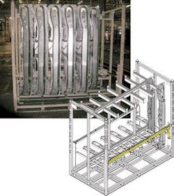
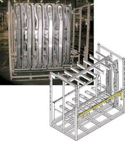
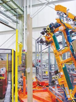
Let’s look at what goes into a completed solution for an auto-racking application. We’ll do this in the context of a case study of a system successfully integrated and installed in a stamping plant. The application is loading completed side sill assemblies into a rack. The side sill is a sheet-metal stamped part about 6 ft long weighing 25 lb. The rack has seven hooks on each side and each hook holds seven parts. When completely filled, the rack is rotated and the other side is loaded (see Fig. 1).
Besides finding the overall location of the rack, the vision system has to ensure the rack is not damaged and acceptable to load without a crash. If the shipping bar is up, the part will crash into the rack. If an arm is bent down, the robot will scrape the part across the bar and damage the part .
On the surface this type of application appears to be a fait accompli—an automation solution that can be purchased off-the-shelf. But seeing a demonstration of feasibility is about 5% to 10% of the total engineering effort it takes to get a fully implemented system in your facility. So if you see a demonstration at a vision show or supplier shop, all you really know is that the vision system is able to locate features on that particular rack and provide offsets to a robot to load a small sample of parts into the rack.
A fully automated cell has to handle all the variation in parts and racks that you will see in production and anything else you can throw at it. A successful application has planned for and tested the variation before installation. The process steps we used at Ford Motor Co. for one such application are
- Define system requirements
- Develop vision solution feasibility
- Optimize overall system process
- Develop hardware/software architecture
- Vision solution development
- Integration & debug
- Validation
- Installation
The process flow for the overall cell operation should be defined. It has to include both defined functions and any possible exceptions to the flow. For example, you might want to design the cell to start loading only completely empty racks. What will happen if the driver drops off a partially loaded rack? How will the automation identify the situation, and what is the next step? Any interaction that requires operator intervention should be closely analyzed.
Since you are developing an automated cell, an operator might not be readily available to fix the situation and resume cell operation. You could lose substantial throughput if the cell sits in an error state for an extended period. Also, there are safety concerns if the operator is expected to enter the area around the robot or the drop off area where the truck drives, or if the fork lift driver has to exit his vehicle to tend to the rack or automation.
Before you get too far down the path, you need to verify the feasibility of using vision to solve this application. At this point, you might want to consider both robot-mounted and stationary cameras. Evaluate the robustness, cost, and complexity of each solution. The shipping rack should be evaluated for strong, repeatable features that can be used to provide offsets.
Different solutions using competing supplier’s systems and various lighting techniques can be analyzed. Determine the camera resolution requirements. The solution with the highest probability of success at an affordable cost should be selected—not necessarily the lowest cost proposal.
Once you understand the issues with the vision application and have selected a vision integrator, it is time for the team to discuss the entire system. An optimal system solution requires trade-offs between the vision, robot, material handling, cell controller, and other automation devices in the cell. By knowing the hardware and software capabilities of the selected equipment, you can determine which equipment handles which tasks.
The entire project team, including vision integrator, process equipment integrator, plant operations, material-handling specialists, and system integrator should meet early and often to develop the concepts and architecture for the overall solution. Repeat steps 1 through 4 iteratively until the team is satisfied that the solution meets the cost, complexity, and robustness targets identified. Decisions made at this point in the project will determine the overall success you will achieve.
Once the architecture is defined, an overall system specification must be written. Be specific. Missing details (that is, just saying that the robot must automatically load parts) can lead to disappointments with the operator interface, calibration procedure, and packaging. If the vision solution for robot guidance is a commercial product—either embedded in the robot controller or a third party PC-based vision system—you have an advantage because you can evaluate the system before you make the decision to purchase. When each subsystem has a specification for its tasks, the vision integrator can then design the specific solution.
Do not underestimate the amount of engineering it takes to provide a good operator interface and calibration procedure. Many suppliers believe their intellectual property is contained in their vision algorithms. In practice, customer satisfaction is determined almost entirely on ease of recovering from problems during production. Vision algorithm performance is simply the minimum requirement to do the application.
The integration, debug, and installation procedures follow standard project management guidelines. While they are also critical to the success of the project, it is not a subject covered in this article.
What We Did
We shipped a rack and some parts to the vision integrator to program a feasibility demonstration. The preferred solution was stationary cameras to eliminate the problem of video cable breakage on the robot. However, because of the size of the rack and the resolution needed for loading, more than 16 cameras would have been required. This made the system too expensive, so we proceeded with a robot-mounted solution with trepidation. Robot-mounted cameras actually turned out to be the easier, lower risk solution.
With our sample parts we determined that the clearance between the part and hook was too tight for reliable operation. More important, we did not have any vision features on the rack to locate the angle of the hook to accommodate the variability caused by age and damage to the racks. Fortunately, the racks were going to be refurbished anyway, and simple inexpensive modifications could be included.
The first thing we did was to reduce the size of the hook. It was the top tab holding the parts in, not the sides, so these were reduced to the width of the bar. Then we added vision targets (fiducials) to critical areas of the rack. Since the racks get damaged and rust over time, we did not want labels or painted-on targets. We had the rack supplier drill holes in the rack for the targets.
The lighting was configured to saturate the surface of the hook, enabling the vision system to look for black holes against a white background. Even if the edges of the hook are damaged or corroded, the features of the hole will be unchanged. The best vision features are those designed right into the product specifically for vision, not just working with what you have. Having the shipping rack designer on the team early enabled us to make these critical design changes (see Fig. 2).
We still had to address our maintenance concern with robot-mounted cameras and the durability of the cables. At other plants we had had to redo the wiring on many robot cells because the cables would break after a few thousand cycles. A decision to use smart cameras instead of PC-based vision had a huge impact on cable simplification and packaging.
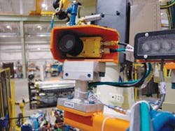
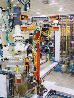
The wiring and controls for the cameras and lights were consolidated in a junction box mounted on the robot arm. Then an Ethernet switch mounted in the junction box further consolidated the wiring. And since the smart camera could trigger the LEDs with on-board I/O, we only had to route two cables on the robot itself—an Ethernet cable and power.
The cable was further sectioned with a junction at the base of the robot, so that if the robot-mounted cable broke an operator would not have to go into the cable trays and fish out the wires. This greatly reduces maintenance time. Compare this to a PC-based vision system and all the wires that would have to be routed, and you can see why people get so excited about smart camera packaging for machine vision. We paid a $15,000 premium to use smart cameras over PC-based vision for this application, but everyone thought it was worth the money (see Figs. 3 and 4).
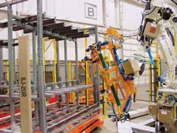
The cell integrator designed the robot end-effector tooling and did a good job of protecting the cameras from a robot crash. Because the smart camera comes in a factory hardened enclosure, it did not have to be put in a separate enclosure, saving both money and weight. A screw-on lens protector cap was used to cover the lens. The integrator provided a heavy gauge guarding around the cameras and lights. Near-infrared LEDs were selected for the lighting to protect the fork truck drivers from the annoyance of flashing lights. These devices are strobed and packaged in a factory-hardened, thermally efficient housing, ensuring their 50,000-hour-rated lifetime exceeds the anticipated life of the cell (see Fig. 5).
If you talk about the robot crashing, robot suppliers will tell you that robots don’t crash—they are reliable and the controllers don’t get out of sequence or go in the weeds. While it might be true that robots don’t crash, people do crash robots. Most crashes happen during or after some maintenance operation. We had two crashes already on this robot, one during system debug and another when there was a damaged rack in the cell and the maintenance operator, attempting to remove the part, got the coordinate frames mixed up. The cameras survived both crashes (see Fig. 6).
Even with smart cameras, the vision system requires a PC to provide an operator interface and do the math calculations of 3-D stereo vision. The PC can also be used to store images of failed operations and data logging. Don’t forget to make the PC robust, since it is required for the operation of the cell. A desktop PC in an enclosure is not an industrial PC. You also need to back up the hard drive, either over the network or with a redundant hard drive.
The programming console for the vision guidance system should be designed for an operator, not vision engineer. While engineers get excited about programming vision systems, operators and skilled trades can be intimidated. Operators should not have to use gray-scale or pixels. Offsets are in millimeters. Make it simple and graphical for ease of use.
HANDLING THE SYSTEM
You will need functions available to handle vision system setup when things go wrong in the cell. A really important function is calibration verification. When the robot can no longer load parts in the right location, the first thing people suspect is what is considered to be the most complex thing in the cell—the vision system.
They will tweak the calibration between the vision system and robot, and usually end up making the problem worse. If you provide a calibration verification function, the operator can test calibration before changing it. One simple push of a button, and the system will say whether the calibration is OK or not. If it is OK, they can look elsewhere for problems.
Another important function is autocalibration. If a calibration target is in the cell, another push of the button, and the system can recalibrate itself without the operator ever having to lock out the cell and enter the work area.
The third function is simplified camera replacement. If you provide graphic overlays, you can guide the repositioning of a camera so that the system will require only minimal recalibration. A post in the cell is our calibration target (see Fig. 7).
The vision system consists of a PC and three smart cameras running under a commercial robot-guidance software package. It is a slave device to the robot controller that gets its commands from the cell controller PLC. All communication is done over Ethernet. The three smart cameras are mounted on the robot tooling: two cameras at the top form a stereo pair to find the hook position and angle and the bottom camera locates the center between the guides.
The vision PC calculates offsets and angles from the location of target fiducials on the front tab and the back of the rack. The front tab establishes the position of the hook so that the robot can center the hole in the part over the tab—similar to threading a needle. The rear fiducial in combination with the front fiducial establishes the angle of the hook. Once the first part is loaded, it is assumed that the angle of the hook does not change for the next six parts on that hook, but the location is measured again for each subsequent part in case the rack was moved between parts. Camera 3 is used to center the 6-ft part between the guide rails at the bottom and the hook at the top.
The cameras also use Ethernet to communicate with the vision PC, but their communication is local and restricted to the vision PC in the cell. The robot controls all motion and positions within the cell and only uses the vision system to provide offsets to the load positions. Using robot-mounted cameras enables a lower-risk, more-robust solution because the magnitude of allowable offset for robot motion can be restricted to what is reasonable for an undamaged rack. If the vision camera should misidentify a feature and make an erroneous calculation, an error would be flagged before the robot was sent to an invalid location.
IN OPERATION
The vision PC initiates an acquire-image command to the smart cameras. The cameras snap the picture, process the image, and return the location of the target it identifies. The intelligence of the system resides in the PC, which under the control of the robot guidance software package, uses the target locations to perform one of its specified functions: calibrate, verify calibration, and provide the robot with offsets and angles for loading parts on the hooks.
Before loading the first part in the rack it is necessary to check for the shipping bar to be in the down position and for the rack to be empty. The team decided not to automatically load partially filled racks. This decision simplified the system design considerably, and fit in with standard production practice. Initially, it was going to be the vision integrator’s responsibility to verify that the rack was ready to load. Vision cameras were considered, but these two checks were actually quite difficult to do with vision.
We decided to use a laser safety curtain to verify empty racks and a laser proximity switch for the shipping bar position. Breaking a through-beam safety curtain is intuitively more straight forward than programming a vision system to look through an empty rack onto the factory floor and verifying no parts are in the rack. The system integrator took responsibility for these two checks, again simplifying the overall system.
This project was successful primarily because the entire team got together early and made good trade-offs in the system design. What could have been a difficult vision solution turned out to be almost trivial for the vision system: finding three black circles against a white background. The most robust automation solutions are those where no detail is overlooked and good engineering principles are used to solve complex problems with the simplest approach.
Valerie Bolhouse was formerly a vision specialist at Ford Motor Company, Detroit, MI, USA. She has presented five Vision Systems Design Webcasts on the Fundamentals of Machine Vision, available on demand at www.vision-systems.com.
null
