Telecentric lenses focus on machine vision
Choosing the right lens requires balancing magnification, performance, weight, and size.
By Andrew Wilson, Editor
In the automotive and electronics industries, parts with complicated shapes must be imaged with high accuracy. When using machine vision to inspect three-dimensional parts, this is especially important. In such applications, conventional lenses may produce distorted images. To overcome such distortion, systems integrators must use telecentric lenses.
Often telecentric lenses are required because conventional lenses cannot accurately portray objects that are off-axis to the lens or are at different distances from the lens. Viewing-angle error and magnification error are inherent in conventional lenses, and these perspective distortions can create significant interpretation problems for software.
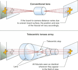
If, on one hand, an image of connector pins is captured with a camera fitted with a conventional lens, the area of the tops of the pins that are farther from the lens will appear smaller. Telecentric lenses, on the other hand, maintain a constant viewing angle at any point across the aperture of the objective lens. If the same image of connector pins is captured with a camera fitted with a telecentric lens, the area of the tops of the pins will remain constant. Because of this, machine-vision systems fitted with telecentric lenses can acquire images of objects that appear dimensionally accurate, regardless of viewing angle or proximity to the lens.
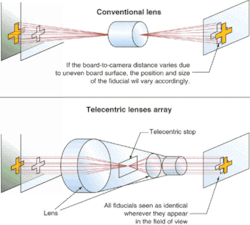
FIGURE 1. Illustrating the effects of telecentric lenses is the Infinity screen printer from DEK. The optic unit within the camera assembly uses telecentricity to ensure that board warping, distance between camera and board, and the position of the fiducials within the FOV do not affect alignment accuracy. With a standard lens, the diameter, centroid, and position of a fiducial vary with this distance. Variations in the distance between the optic unit and the board fiducials due to uneven board surface are transparent when using telecentric lenses.
In applications in which viewing-angle and magnification errors need to be minimized, telecentric lenses maintain magnification and viewing angle to the subject as long as the part stays within the depth of field (DOF) of the lens. By eliminating perspective distortion, telecentric lenses produce a dimensionally accurate image that software can interpret (see Fig. 1).
Choosing a lens
In choosing telecentric lenses, systems designers must be aware of the number of different types and their applications. Perhaps the most commonly referred to type of lens has a telecentric structure on both object and image side. These are often referred to as doubly telecentric or afocal lenses and may require a large number of lens elements in their design. Because these lens systems are telecentric on both sides, they are ideally suited for precision measuring applications where the position of both the camera and the part being inspected need not be rigorously defined.
To lower the cost of these lens systems, many vendors offer object-side telecentric lens systems, which are only telecentric on the object side. In such designs, the focal length of the lens on the image side appears as it would in an ordinary camera. And, because the cameras are designed in this manner, fewer lens elements are required, resulting in lower cost. However, the accuracy of these lens systems may be less than that of doubly telecentric lenses, since greater care must be taken in fixing the sensor or camera to the image side of the lens.
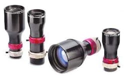
One of the most important parameters used in specifying a telecentric lens is the magnification DOF. Edmund Industrial Optics, for example, has designed four MVO object-side telecentric lenses with magnifications of 0.125, 0.25, 0.5, and 1.0x. These lenses yield constant magnification over a defined DOF and are optimized to provide <0.1° telecentricity when used in the lenses' specified working distance range (see Fig. 2). Anywhere within this range, the same magnification can be obtained by refocusing. Because maximum FOV in telecentric systems relates to the lens aperture closest to the object, larger front lenses are necessary for larger FOVs.
For most machine-vision applications, an object-space telecentric lens is all that is needed. "However," says Jeff Harvey, marketing manager at Edmund Industrial Optics, "we found a number of customers that had issues with what we call chip-dip-tilt. Basically, the customer had such precise inspection applications that distortion was being noticed because of the way the CCD is mounted in the housing. This dip and tilt caused some image-space distortion, and so an afocal telecentric lens was used to remove it."
Most of the lenses produced by Light Works LLC are of the doubly telecentric type. Examples include the company's Super-Eye line of long stand-off lenses and large-field-of-view wide-eye line of telecentric lenses. Light Works also builds custom lenses such as its latest extreme-depth-of-field lens. This is a unit with a nominal magnification of 0.028x and a nominal stand-off distance of 12 ft. Over a range of ±10-ft object distance change, the magnification changes by ±0.15%.
Telecentric zooms
Because the image side of the lens in an object-sided telecentric lens system can be varied, such designs can be modified to form telecentric zoom lenses. In such designs, telecentricity may remain on the object side of the lens while the focal length on the image plane can be changed to increase or decrease the magnification of the lens. These lenses are generally offered in versions to allow the zoom factor to be manually or automatically controlled. Such lenses are especially useful in applications where object telecentricity remains fixed while the image size must be increased or decreased to make a measurement.
"To design a telecentric zoom lens," says Harvey, "you need to move the front-end optics (in the case of an object-space telecentric lens) and the stop in-between the front and rear lenses." The difficult part of this is that, to maintain the telecentricity of the system, the stop and the optics move at different rates. "This can be a mechanical design challenge, as smooth movements for both the stop and the optics must be maintained. This is a major reason why a lot of zoom telecentrics are not available on the market," Harvey adds.
Several other companies also offer telecentric lenses for machine-vision applications with a range of magnifications, focal lengths, and flange mounts. While most telecentric lenses are now being offered in fixed-focal-length versions, variable-focal-length or zoom lenses permit developers of high-precision semiconductor-measuring equipment, for example, to zoom in and focus over a variety of magnifications while retaining a high level of accuracy.
With a magnification of between 0 and 125x and 0 and 5x, the Sill Optics lens works with 1/2-in. CCD and CMOS matrix sensors and allows a continuous adjustment of its working area from 51.2 × 38.4 mm to 12.8 × 9.6 mm. Navitar also produces a telecentric zoom lens that features a 12x telecentic zoom to within less than 0.3° while maintaining constant perspective and magnification. The 12x lens provides field coverage from 4 to 50 mm.
Of course, telecentric lenses can be built so that telecentricity is on the image side, in which case, the lens is said to be image-side telecentric. Here, the focal length of the lens on the object side appears at it would in an ordinary camera, and the lens system has telecentricity on the imaging side. The principal rays arrive at the lens in parallel to the optical axis, and image-plane movements to focus or defocus the system will not change the image size. However, these lenses are rarely used in machine-vision applications because they are more suited to orthographic semiconductor projection systems.
Illumination methods
When inspecting metallic or reflective surfaces, careful attention must be paid to the illumination used with telecentric lenses. When standard lenses are used in machine-vision systems, any coaxial illumination used to highlight the images will not be exactly parallel, resulting in an off-axis reflectance. When illuminating objects such as the surface of silicon wafers or CDs, this type of lighting may not highlight specific defects. When used with a telecentric lens, however, the effects of coaxial illumination will result in parallel illumination that can show defects.
A number of lens manufacturers offer some form of coaxial illumination with their lenses. In the case of Sill Optics, all of the company's telecentric CCD lenses with a magnification of <1.0 are available with coaxial surface illumination, which is integrated in the lens and allows telecentric illumination directly through the lens. This light is provided either through coupling with fiberoptic or an LED illumination system.
Alternatively, as is the case with Opto Engineering, coaxial diffuse light illuminators can be added using a specialized mechanical interface. Opto Engineering's telecentric lenses are designed to allow enough room between the illuminator outer surface and the object to be imaged. One advantage of these illuminators is their interchangeable illumination geometry—the illuminator can be set to have the object and the lens on the same axis or to have the object and the lens at 90°.
Despite their inherent advantages in machine-vision systems, telecentric lenses are not a panacea for every imaging application. Objects to be imaged with telecentric lenses cannot be larger than the lens itself or border rays cannot enter the lens parallel to each other. Because of this, telecentric lenses can only be built for relatively small objects since they can quickly become large, heavy, and expensive as the size of objects to be imaged increases.
"Afocal telecentric lenses tend to be heavier than object-side telecentrics because of the size of the optics," says Edmund's Harvey. "If you need a lens that is telecentric across a 4-in. FOV, for example, then the front optics will have to have a diameter of more than 4 in. In an object-space telecentric lens system, a large-diameter optical assembly would be required for the front-end optics, but the back-end optics might be one lens with a 20-mm diameter. In a doubly telecentric system, that single lens may have to be replaced with a telecentric optical assembly of four to five lenses of the same diameter, adding to the weight of the lens."
Company Info
Due to space limitations, this Product Focus does not include all of the manufacturers of the described product category. For information on other suppliers of telecentric lenses, see theVision Systems Design Buyers Guide(Vision Systems Design, Feb. 2003, p. 72) or the Web site: www.vision-systems.com.
Carl Zeiss, Oberkochen, Germany, www.zeiss.com
China Daheng Corp, Beijing, China, www.cdhcorp.com
Computer Optics, Hudson, NH, USA, www.computeroptics.com
Edmund Industrial Optics, Barrington, NJ, USA, www.edmundoptics.com
Goyo Optical, Asaka, Japan, www.goyooptical.com
Jenoptik, Jena, Germany, www.jenoptik-los.de
Kyocera, Somerset, NJ, USA, americas.kyocera.com
Lightfarms, Denton, TX, USA, www.lightfarms.com
Light Works, Toledo, OH, USA, www.LW4U.com
Linos, Göttingen, Germany, www.linos.de
Melles Griot, Rochester, NY, USA, www.mellesgriot.com
Moritex, San Jose, CA, USA, www.moritex.com
Myutron, Tokyo, Japan, www.myutron.com
Navitar, Rochester, NY, USA, www.navitar.com
New Electronic Technology, Finning, Germany, www.net-gmbh.com
Nikon Instruments, Melville, NY, USA, www.nikonusa.com
Opto Engineering Srl, Mantova, Italy, www.opto-engineering.com
Schneider Optics, Hauppauge, NY, USA, www.schneideroptics.com
Sill Optics, Wendelstein, Germany, www.silloptics.com
Thales Optem, Fairport, NY, USA, www.thales-optem.com
Visicon, Napa, CA, USA, www.visicontech.com
Vision and Control, Suhl, Germany, www.vision-control.org


