Sensor checks IC position prior to board insertion
Inserting an integrated circuit (IC) in an incorrect orientation on a printed-circuit board (PCB) can cause costly assembly rework or turn the PCB into expensive scrap. To overcome this production problem, Banner Engineering Corp. (Minneapolis, MN, USA; www.bannerengineering.com) has worked with a board manufacturer to ensure that packaged ICs are properly inserted and positioned. The company's PresencePLUS Pro Vision sensor, combined with LED lighting devices, is built into a vision-inspection system that determines the orientation, labeling, and pin count of every IC before it is inserted into a PCB.
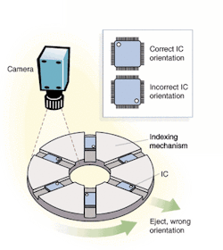
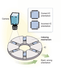
The sensor verifies printed information on a correctly oriented IC. During sensor operation, a region of interest is drawn for the area of printed information. This area registers the highest white pixel count. When the IC is positioned in any of the other three possible orientations, the resulting white pixel count is low. In this case, the sensor cannot verify the printed region, and the IC is ejected by an indexing mechanism (see figure). This sensor also inspects for the correct pin count on the IC package, and, similarly, rejects any IC that does not contain the correct number of pins programmed for that particular part.
Dan Holste, research-and-development manager for vision products at Banner Engineering, says the PresencePLUS Pro comprises a sensor camera head and a controller that can store 12 different inspections, all with multiple software tools. The sensor's camera incorporates a 1/3-in. CCD imager that delivers 640 × 480-pixel images. The sensor head is linked to the controller by a cable, which is impedance-controlled to ensure that high-speed digital data are correctly received by the controller. It can be mounted as far as 10 meters away from the controller.
PresencePLUS Pro graphical-user-interface (GUI) software loads the inspection parameters into the controller from a PC over an Ethernet or serial connection. The PC is not needed during inspections because the inspection sequences are stored in controller memory. The inspections are selected by an operator via discrete inputs through the assembly line's programmable logic controller (PLC) or through the GUI.
Illumination control
Strobing of the red LED lighting devices used in the IC inspection application is programmed into the controller before the inspection process is started. The parts under inspection are indexed into position under the camera, where a photoelectric eye detects the part's presence. The part is stopped momentarily by the inspection system's PLC, an exposure is made, and the sensor sends a pass or fail signal back to the PLC. In turn, the PLC allows the passed parts to move on for eventual insertion into a PCB or signals the ejection of the failed parts by an indexing mechanism.
Banner Engineering provides all the hardware and software for the IC inspection station—sensor, controller, integrated cable, and PresencePLUS Pro inspection software. According to Holste, the user provides the control system that drives the PLC, as well as the indexing mechanism. "They are responsible for part presentation, and this application is all about good presentation," he says.
In this application, "Lighting is a big challenge in a tight space," Holste says. "It's important to get images that are not saturated and are repeatable. We use lighting to highlight the regions of interest and we try to downplay features that are not of interest."
Timing of the photoelectric eye and strobing of the LED illuminators are essential to getting good images. To that end, the software permits the user to modify both. The camera and the pattern-recognition software can sense if a part is properly labeled, the pin count and spacing are correct, and there are no bent pins.
Holste says Banner Engineering's system replaced a costlier custom system that included a camera, frame grabber, and PC. "We believe we've provided an affordable solution to an industrywide application that has long been a challenge," Holste contends.
Lawrence J. Curran,
Contributing Editor

