Lighting setup aids web inspection of rolled steel
Lighting variables in machine-vision web-surface inspection systems must be evaluated before cold-rolled-steel defects can be identified.
By Mike MuehlemannThe global push for higher product quality continues to drive the demand for automated inspection systems. High-technology users such as those in the semiconductor and electronics industries were the early adopters of machine-vision inspection technology. After paying the
costs associated with initial learning, they realized significant return on investment from the use of these technologies. Increasingly, more-traditional industry sectors are adopting refined inspection tools to improve their overall product quality, their customers' satisfaction ratings, and, ultimately, their bottom lines.
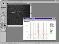
FIGURE 1. The automated surface inspection of steel strip is commonly performed on a cold mill. These mills, which include Pickle Lines, Tandem Mills, and Temper Mills, typically are 2 m wide and operate at top speeds from 1200 to 4000 ft/min. At the data rates that these applications produce, improvements in the defect signal-to-noise ratios translate into improved system reliability and final product quality. The structure of the input lighting plays a key role in determining the signal-to-noise ratio for the various detected defects.
One such industry is the rolled-strip steel industry. While much of basic steel production has moved offshore, steel makers in the United States and Europe have focused on producing high-end products combined with increased production efficiencies to maintain profitability. Escalating pressures toward "zero-defect" rolled material, driven predominantly by the automotive, appliance, and furniture markets, have forced steel manufacturers to provide higher levels of product quality. These end users make up the largest industry sector for cold-rolled strip products, which are produced on high-speed webs of up to 2 m in width. Of primary interest to these end users is the surface quality of the rolled strip, which has significant impact on the outcome of their finishing operations, whether painting, plating, or other (see Fig. 1).
Simple surface defects in the rolled strip, such as pits, bumps, scratches, and holes, create obvious problems for finishing operations; however, more problematic is the fact that in many production lines these defects do not become visibly noticeable until an operation is completed. This situation adds complex and expensive rework steps for end users that reduce efficiency and increase production costs.
Other more-complex surface defects such as laminations and oxidation can cause greater problems. These surface defects look proper in the finished product but can suffer rapid corrosion failure rates once the product is in the field. Obviously, failures give the manufacturer a stigma of poor quality that is costly, hard to quantify, and difficult to rectify.
FIGURE 2. During the interaction of light at the steel interface, photons impinging on the steel surface can be specularly reflected, diffusely reflected, backscattered, or absorbed within the material. The position of the camera with respect to the incoming light determines whether the system is in brightfield or darkfield mode. In brightfield mode, defects appear dark within a bright background. Conversely, in darkfield mode, defects appear bright within a dark background.I = incident ray of light; R = the angle of reflection; DR = diffuse reflection; BS = backscattered radiation.
To manufacture products with as few defects as possible in a cost-effective manner, these manufacturers have turned to on-line machine-vision inspection systems. Inspection requirements for surface-critical steel continue to press the limits of current machine-vision technologies. However, the combined developments in linescan-camera technologies, high-speed acquisition hardware, and powerful software algorithms provide the necessary capabilities to meet the speed, resolution, and classification requirements demanded by high-speed webs. Yet in many cases, these systems are still only capable of detecting 50%-65% of all the defects present.
Even with proper cameras, lenses, hardware, and software, the surface-inspection problems presented by the cold-rolled steel industry are nontrivial. The major reason centers on the wide variability obtained in the signal-to-noise ratio (S/N) that each of the many types of defects exhibits as a function of the incoming lighting structure when viewed by the camera system. These defect signals, or lack thereof, are a direct result of the lighting structures used for their potential detection and the variability among similar defects.
To demonstrate and quantify these defects, a study was conducted to examine the effects that lighting variables have on the defects of interest. The purpose of this study was to identify the basic classes of defects that are to be detected and establish quantifiable recommendations for lighting structure(s) that maximize the signal-to-noise ratios for these defects.
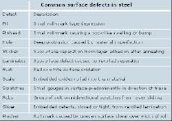
The key to the successful implementation of a machine-vision application relies on a thorough and complete knowledge and quantification of all the defects (or features) of interest. Cold-rolled steel develops a range of surface defects that must be detected, recognized, and classified. While there is a range of potential defects, "trade names," and classifications, the study focused on the defects and their associated descriptions delineated in the table (on p. 40).
Interaction of light
To understand the interaction of light with steel, researchers first investigated how incoming light interacts with a typical piece of steel (see Fig. 2). An incident ray of light impinging on an arbitrary opaque material either enters the material, is reflected, or separates into a combination of transmitted and reflected components. The portion of the incident beam that enters the material is either transmitted through the material or is absorbed within the material in a ratio defined by the specific optical properties of the material itself. Because steel is a conductor, a large percentage of the light is reflected from its surface, small light components are absorbed, and virtually no light is transmitted through the steel sheet.
FIGURE 3. In a laboratory test setup, a focused lightline and a digital camera are precisely positioned using a specialized protractor style fixture assembly. Signal strength and signal-to-noise data are then acquired for all possible lightline and camera angles.
If the steel surface is perfectly smooth and shiny, a high percentage of the light is reflected. Most of this reflection is specular, which means that the angle of incidence equals the angle of reflection. If the surface is machined, rolled, granular, or has a micrograin structure, a portion of the reflected light is reflected in directions other than specular. When the scattered light leaves the surface on the same side of the normal as the specular component, but is not purely specular, then this behavior of the light is called diffuse reflection.
FIGURE 4. A "hole defect" demonstrates the primary characteristic of a typical brightfield defect. It is dark, while the background is bright. The background noise level for brightfield defects tends to be large for steel samples due to the granular nature of the surface.
A camera viewing the surface from this side of the normal is said to be viewing in brightfield mode, because the image of the surface tends to be bright from the abundance of reflected light that enters the camera. If there is any form of defect on the surface that prohibits (or otherwise degrades) the "perfect" reflection of the brightfield illumination, then the camera will detect this defect as a dark area within a light background. Such is the case for geometrical defects that tend to divert light from the camera (reflect it in a different direction) and for embedded material defects that tend to absorb rather than reflect light back to the camera.
FIGURE 5. A "lamination defect" demonstrates the primary characteristic of a darkfield defect. It is brighter than the dark background. The background noise level for darkfield defects tends to be less for steel samples due to the relative reflective nature of the surface. Because most of the light is reflected outside the field of view of the camera, these darkfield defects require much higher incoming light intensities.
When the scattered light leaves the surface toward the same side of the normal as the incident radiation, this light behavior is called backscattered radiation. When the light travels straight back upon the incident radiation, then this special case is called retroreflection. A camera viewing the surface from this side of the normal is said to be viewing in darkfield mode because the image of the surface tends to be dark when the majority of the reflected light does not enter the camera. If there is a defect on the surface that causes light to be backscattered, then the camera will detect this defect as a light area within a dark background. Such is the case for several classes of geometrical defects that tend to divert light from the incident beam (reflect it in a different direction).
Test setup
To measure the lighting effects for each defect type, the camera and lighting devices (fiberoptic lightline with cylindrical focusing lens) were mounted on a large protractor-type fixture, with the samples placed at the focal point (see Fig. 3). This geometry allows the projected line of light to remain fixed at the sample plane as it is rotated throughout the testing angles. In a similar manner, the camera remains in focus as it is rotated throughout various test angles. The angles are designated from the normal: positive values are in the clockwise direction, and negative values are in the counterclockwise direction.
FIGURE 6. A "scratch defect" demonstrates the primary characteristic of an oblique defect. The defect is much brighter than the dark background, and the background noise level is characteristically darkfield. These defects are invisible (S/N = 1) under typical brightfield or darkfield modes because they tend to be aligned parallel to the direction of web travel.
The data are recorded after the camera and lightline are fixed in position. The data are extracted from an 8-bit digital image using a line profile (histogram) across each defect and for each possible combination of angles. Each angle is varied (one at a time) by 10°, and a new reading is acquired until all combinations have been covered. The procedure is then repeated for each of the listed defects. The line histogram provides a quantitative measure of the signal-to-noise ratio for each defect and geometrical configuration.
Defect types
Brightfield-mode defects typically exhibit dark defects in a light background (see Fig. 4), although the background creates noise due to the less than perfect reflecting surface caused by the granularity and the crystalline nature of the material. In general, the background noise level can be high due to the granular nature of the defects. The amount of light is not a serious concern for these defects because a large percentage of the incident light is reflected directly into the camera.
Darkfield-mode defects typically exhibit lighter defects within a dark background (see Fig. 5). Here, the background noise is generally much less than in brightfield mode, which helps to improve the S/N. However the signals developed from the defects themselves can be less than ideal due to the less efficient method of getting light to the camera. In this case, the amount of light required is of major concern because a large amount of the emitted light is reflected away from the camera and never used.
Oblique-mode defects are basically a darkfield defects in the cross-web direction (see Fig. 6). They exhibit a low background noise, but generally provide high signal levels due to the nature of the defect and because the reflecting sides of the scratches behave more specular than many of the other darkfield defects. Accordingly, the amount of light required by the oblique mode is not as critical because a large amount of the emitted light is reflected directly into the camera in the region of a defect.
Data definitions
After the raw data were acquired, two evaluation criteria were established. The S/N was defined as the maximum pixel value in the histogram minus the minimum pixel value divided by the maximum noise spike minus the minimum pixel value. In all cases, this definition yields a conservative estimate of the S/N for a given histogram.
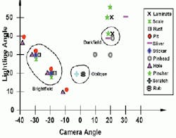
A dynamic range variable was also established. Delta was defined as the difference of the maximum pixel value in the histogram minus the maximum noise spike in the histogram. Once compiled, all configurations for which the S/N was greater than 1.8 and Delta was greater than 40 were graphed as functions of the lighting angle versus the camera angle (see Fig. 7).
Data analysis
After the data were plotted, several parameters become apparent. First, there is no one lighting/camera configuration that can deliver all the defect images to the camera with desirable signal-to-noise ratios. However, all defects can be detected if they are cordoned off into three basic groups: brightfield, darkfield, and oblique.
While some of the brightfield defects can be seen for almost any set of brightfield angles (pits and holes), all brightfield defects present a common union for mating camera and lighting angles between 20° and 30°, as measured from the opposite sides of normal. The four darkfield defects exhibit a more narrow common union for camera angles near 20° and lighting angle near 40°, as measured from the same side of the normal.
The only two defects that do not appear within either of these groups are scratches and rubs. These types of defects have historically created problems for automated inspection equipment because of their specific nature. In many cases, these defects tend to be aligned parallel to the direction of web travel, creating a situation that offers little or no contrast for any camera angle because of even illumination in the cross-web direction.
FIGURE 7. Defect analysis was performed as a function of camera and lighting angles. The results of the study illustrate the complexity of the problem. There is no one set of camera and lighting angles that will deliver high contrast images for all defects. However, even the difficult parallel defects can be detected with high signal-to-noise ratios if the Oblique Lightlines technique is implemented.
In fact, the only way discovered to improve the contrast ratio for these types of defects was to develop a cross-web lighting component (or side light) using a patented method called Oblique Lightlines. These special asymmetric lightlines introduce a cross-web illumination component that produces a darkfield illumination mode for small scratches aligned parallel to the direction of web travel. By including the third or oblique group, all the defects of interest can be detected with more than adequate signal levels.
Future concerns
The study discloses that independent lighting and camera modes must be implemented if all of the above rolled-steel defects are to be inspected with peak-detection probability, thereby ensuring system reliability. The 20° camera angle is common for both the brightfield and darkfield lighting modes; however, these lighting modes are not independent because they affect one another. Specifically, the brightfield mode eliminates most if not all of the contrast gained by the darkfield mode.
Although one lighting system may be used, two banks of cameras must be used to catch all brightfield and darkfield defects. Another study observation discloses that darkfield defects require almost eight times the amount of light as brightfield defects. This requirement is sometimes overlooked in practice, but it has important implications for the cost and lifetime of a single lighting system should a common one be selected for both modes.
Oblique mode requires a completely independent lighting system. Preliminary data suggest that oblique mode also mandates an independent set of cameras. Future work will focus on integrating the Oblique Lightlines technique in conjunction with the darkfield camera bank. Such a configuration might prove able to detect all the defects using a favorably balanced detection system.
Future work will also focus on the effects of the parallax errors caused by the camera field of view in the cross-web direction. This work will also help determine the optimum number of cameras to be implemented for a particular application, independent of pure resolution issues. Future studies will also evaluate statistically significant data sets for each defect type in an effort to establish tighter definitions of the three modes, based on reasonable variations in the defect classes themselves.
Some interesting effects occur for some of the brightfield defects. Slight variations from the true specular angle (1° or 2°) result in considerable improvement in the signal-to-noise ratio for some of these defects. This slight adjustment from the true brightfield angle is sometimes referred to as the "twilight angle." More work needs to be done to understand the nature of these anomalies, their variation among similar defects, and their variation among other classes of brightfield defects.
The steel-strip industry is benefiting greatly from implementations of sophisticated machine-vision-based surface-inspection techniques. Systems integrators, suppliers, and end users should expect to see significant progress in the burgeoning web-inspection market as many traditional industries begin to apply the full potential of these technologies.
MIKE MUEHLEMANN is president of Illumination Technologies Inc., East Syracuse, NY 13057; e-mail: muehlemann@illuminationtech. com.


