Multiple sensors detect land mines
Combining visible-light, infrared, electromagnetic-induction, and ground-penetrating radar-sensing technologies automates the detection of buried land mines.
By Andrew Wilson,Editor
At present, military analysts estimate that approximately 65 million land mines are buried in more than 60 countries. They also project that each year more than 2 million new land mines are deployed, while only about 100,000 land mines are cleared. The effects on human lives are horrific—more than 25,000 people are maimed or killed each year, mostly in Angola, Mozambique, Cambodia, and Afghanistan. Now, three years after 121 nations signed a treaty to ban antipersonnel land mines, many nations are still looking at cost-effective methods to automate the detection, removal, and disposal of these dangerous devices.

Current land-mine-detection methods include the use of metal detectors, trained animals, brute-force detonation methods, and hand-held mechanical prodders. Most of these approaches are mechanical, slow, perilous, and suffer casualties and high false-alarm rates. To overcome these limitations, researchers at the Defence Research Establishment Suffield (DRES; Medicine Hat, Alberta, Canada) and at other Defence R&D Canada (DRDC) labs have developed a land-mine-detection system that combines information from several sensor technologies, including infrared (IR), visible, and ground-penetrating radar (GPR).
The most important criteria in the selection of detectors were a high probability of detection, low technical risk, low cost, and the ability to fuse data together after collection. In the operation of the DRES Improved Landmine Detector Project (ILDP), these sensors deliver independent outputs so that multiple alarms are needed to indicate the presence of a mine, even though any single detector could occasionally trigger a false signal.
SYSTEM DESIGN
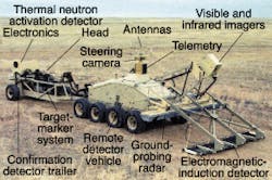
Because it was necessary to develop a detection system that could be operated remotely, DRDC researchers commissioned Q Sine (Calgary, Alberta, Canada) to develop an eight-wheel hydrostatically powered vehicle on which to mount the sensors (see Fig. 1). This vehicle provides electrical and hydraulic power to all the subsystems, including those for electromagnetic induction (EMI), IR, visible light, GPR, and thermal neutron analysis (TNA).
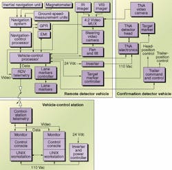
Rather than build a metallic-based detection system, the ILDP uses the Vehicular Array Mine Detection System (VAMIDS) from Schiebel (Vienna, Austria). In the VAMIDS, a sensor-head array consisting of 24 overlapping transmit/receive coil pairs are pushed in front of a moving vehicle by a frame that projects outward from the front of the vehicle. After pickup signals from the sensors are digitized by the sensor control cards located in the VAMIDS control unit, sensor data are processed using proprietary algorithms. These tools can detect a located object to within approximately 10 cm. The data are then transmitted to the ILDP vehicle control processor over the VAMID system's RS-232C port (see Fig. 2).
At the same time EMI data are being collected, both thermal and visible images are being captured. Located above the EMI sensor array is a weatherproof container that houses an IR imager and a visible-light CCD camera. The IR imager is a modified Agema 1000 camera from FLIR Systems (Portland, OR); it operates over an 8- to 12-µm wavelength band with a field of view of 62° across and 41° along the track. After these images are multiplexed, they are transmitted via an on-board spread-spectrum telemetry system from Freewave Technologies (Boulder, CO) and a video-transmission system from Premier Wireless (Antioch, CA) to a vehicle-control station located hundreds of meters from the detection vehicle.
Positioned behind the IR/visible-light camera mount is the antenna of the GPR detector from Elta Electronics (Ashdod, Israel). Based on the Elta EL/M-2190 detector, the GPR system is 3 m wide and mounted 70 cm above the ground surface in a horizontal orientation in front of the vehicle. The GPR signals the location of a target relative to its antenna position and a target confidence level, which is an indication of how "mine-like" the GPR perceives and classifies the potential target. These data are then transmitted to the vehicle-control processor over an RS-232C port and sent via the telemetry system to the vehicle-control station.
DATA FUSION
System command and control functions are performed remotely at the vehicle-control station located several hundred meters away from the remote detector vehicle. The same telemetry system used to receive detector data from the remote vehicle is also used to transmit control data for steering the vehicle. At the vehicle-control station, video and data signals from the remote vehicle are transmitted to two Sun Microsystems (Mountain View, CA) SPARC UNIX workstations. While one workstation console displays the image from the remote vehicle's on-board camera and movement controls, the second workstation displays data that has been fused from the different sensors on the remote vehicle (see Fig. 3).
When a target is discovered, the technician moves a cursor over the target to classify the signal as strong or weak. If the target signal is weak, the operator can switch the data input to view the visible image captured by the remote vehicle's CCD camera. After a reliable target is indicated, it is tracked by a custom target-tracking algorithm, which transforms the target's coordinates using navigational information to a local world-based coordinate system.
As the vehicle advances, the area scanned by the IR camera moves into the field of view of the electromagnetic detector. This action produces an intensity map where pixel sizes are related to the width of the sensor coils and the speed of the vehicle. At the vehicle-control processor, this intensity map is analyzed by an automatic target-detection algorithm. Coordinates of suspected targets—some of which correspond to targets indicated by the IR imager—are then overlaid onto the IR data and displayed on the UNIX workstation at the vehicle-control station.
After moving from the field of view of the electromagnetic detector, the GPR scans the area of interest, producing a return-signal intensity map similar to that of the electromagnetic detector. Based on local shape and intensity information, features of this map are analyzed and output as a set of coordinates at a particular confidence level. Once converted to real-world coordinates, these data are also overlaid over the previous data obtained from the IR camera and the electromagnetic sensor. Such data fusion allows the technician to visualize the data from all the sensors as the remote detector vehicle moves forward.

MINE CONFIRMATION
Once a suspect target has been confirmed, a fourth method of detection is used to confirm the presence or absence of a land mine. Mounted on a trailer behind the detector vehicle is a thermal neutron activation detector designed by Science Applications International Corp. Canada (SAIC; Canada; Ottawa, Ont., Canada), Bubble Technology Industries (BTI; Chalk River, Ont., Canada), and the DRDC. It was built by BTI and consists of a detection subsystem, which sits on a moveable carriage, and a computer-based signal processor.
The TNA system is used to detect the level of nitrogen present in the soil. Because all explosives contain a mass of between 15% and 40% nitrogen, the detection of high levels of nitrogen provides an indication as to whether a land mine is present. Using a 100-µg Californium-252 neutron source, the TNA system surveys the area of interest for neutron radiation. Upon thermal neutron capture, any nitrogen present emits a number of gamma rays that are sensed by a ring of four 7.62 x 7.62-cm custom-built sodium iodide detectors. For land-mine detection, the highest energy transition of these gamma rays occurs at 10.835 MeV.
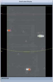
FIGURE 3. Transmitted visual data from the remote vehicle's CCD camera are overlaid with system controls and indicators at the vehicle control station (top). Data fused from the system's on-board sensors show signal data received from the individual detectors (right). Detection data from the infrared sensors are shown as squares, from the electromagnetic induction detector as circles, and from the ground penetrating radar as triangles.
During operation, the TNA system first obtains a background spectrum. Then, the TNA detection subsystem is moved to the target location of interest, which may or may not contain a land mine. Next, another set of spectra is acquired. After this acquisition, the probability of the presence of a land mine is calculated by the TNA system based upon the number of excess counts in the area of interest. These data are then transmitted to the vehicle-control processor where it is fused with data from the other sensors. A final data-fusion algorithm indicates to the technician the probability of the presence of a land mine. Data-fusion algorithms were custom-designed and implemented, as was the vehicle-control station, by DRES. Several software tools including C++, LabView, MatLab, and IDL were used in various stages and components of the system development.
The ILDP was a top performer in the US Department of Defense Advanced Technology Program trials at Aberdeen, MD, and Soccoro, NM. Four production systems, based on the ILDP design, have been ordered by the Canadian Forces and are currently undergoing trials at DRES.
COMPANY INFORMATION
Bubble Technology Industries
Chalk River, Ont., Canada K0J 1J0
Web: www.magma.ca/~bubble
Defence Research Establishment Suffield
Alberta, Canada, T1A 8K6
Web: www.dres.dnd.ca
Elta Electronics Industries Ltd.
Ashdod 77102, Israel
Web: www.elta-iai.com
FLIR Systems
North Billerica, MA 01862
Web: www.flir.com
Freewave Technologies
Boulder, CO 80301
Web: www.freewave.com
Premier Wireless, Inc.
Antioch, CA 94509
Web: www.premierwirelessinc.com
Q Sine
Calgary, Alberta, Canada T2B 3K7
E-mail: [email protected]
Schiebel Instruments
A-1050 Vienna, Austria
Web: www.schiebel.com
Science Applications International Corp. (SAIC)
Ottawa, Ont., Canada K1P 5Y7
Web: www.saiccanada.com