Software techniques aid 3-d imaging in digitizing-scanner Design
Software techniques aid 3-d imaging in digitizing-scanner Design
By Michael Petrov
Traditionally, photorealistic three-dimensional (3-D) digitizing is performed by complex, mechanical robotic devices assembled from highly accurate mechanical components. In a new approach, MetaCreations Real Time Geometry Laboratory (Princeton, NJ) has simplified 3-D scanner-hardware design with custom-software techniques. These techniques have been used to obtain 3-D digitizing by joining all scanning-control and image-processing algorithms into a single 3-D scanner called RealScan 3D (see Fig. 1).
This scanner is based on structured-light-based triangulation principles. In this method, laser-light stripes are deflected by a galvanometric motor, reflected from the object, and digitized by a monochrome charge-coupled-device (CCD) camera. Because the geometric parameters of triangulation distance, galvanometric-motor position, and CCD-detector dimensions are known through calibration, the geometry of the points along the stripe illuminated by the laser can be computed. The 3-D digitizing is performed by scanning the laser 200 or more times across the surface of the object. In addition, a separate color camera is placed between the laser source and the monochrome camera to develop a colored texture map of the obtained 3-D model.
Although laser triangulation is a highly accurate scanning technique, it suffers from a low data-acquisition rate when 30-frame/s CCD cameras are used. When using a CCIR (International Radio Consultative Committee) standard camera, for example, digitizing a 200-stripe scan can take more than 3 s. This rate is not acceptable in image-recognition applications that call for scanning human faces, for example, in which the acquisition time must be less than 1 s.
To reduce the scanning time of such objects, multiline-scanning techniques have been developed by Meta Creations Real Time Geometry Laboratory and Real 3D for the design of the RealScan 3D scanner. These techniques take advantage of the fast speeds available from a galvanometric motor, which can position laser stripes to several thousand positions per second; the video rate of the CCIR camera is much slower. Because the galvanometric motor is the only moving scanning part in the RealScan scanner, its angular positioning capability must be reproducible to about 20 mrad.
The RealScan 3D scanner combines off-the-shelf cameras, structured lighting, custom image-processing algorithms, and multiline laser scanning. During scanning, its laser is repositioned several times within a single video frame, while the video camera integrates the incoming light signals. The camera`s output therefore provides the equivalent of a simultaneous exposure of laser stripes with reduced intensity.
Multiline scanning becomes practical for digitizing live objects when subsecond scanning time is needed. At such scan rates, the digitization time for a human face with 200 lines is 0.8 s. This acquired face scan contains about 25,000 data points, thereby providing high visual and geometric object quality of its 3-D model.
Most laser modules contain a cylindrical glass rod in front of the laser source. This approach results in a projected laser line with a Gaussian intensity distribution. However, for many structured lighting applications, Gaussian intensity distributions are less than ideal. For these reasons, a non-Gaussian 675-nm line generator from Lasiris (St. Laurent, Canada) was selected because it uses an optical element to produce a uniform intensity across its line length.
To detect the geometry of the object being scanned, the VCM 3405 CCIR monochrome camera from Philips (Eindhoven, The Netherlands) is used with a narrow-bandpass filter to eliminate ambient light. Because monochrome cameras typically possess higher light sensitivity than color cameras and work with bandpass filtering, a two-camera subsystem allows the use of a low-power laser source in multiline scanning mode.
An XC-003 3-CCD NTSC video camera from Sony Image Sensing Division (Montvale, NJ) is used to preview the scene and capture a snapshot (texture) of the object with 485 lines of vertical resolution. This camera was selected because of its high pixel quality and because the size of the texture map greatly affects the data-manipulation speed of 3-D computer models. Controlled through host software, this CCD camera also allows automatic focusing, white balance, and iris and exposure settings.
In operation, the resolution of the RealScan 3D scanner runs about 0.5 mm in the x-y-z directions when the object is 50 cm away; this resolution decreases linearly with distance. Scanner distance-measurement accuracy is 0.5%, allowing the objects being digitized to be up to 2 m from the scanner. Accuracy of the texture mapping is about 1 mm. The main source of random errors in the video signals resides in the speckle structure of the laser stripe.
Image processing
Each frame of the monochrome-camera video data contains an image of one or several laser stripes (see Fig. 2a). Because every laser stripe has a final width measured in tenths of millimeters, its signal extends over about five pixels on the image detector. To perform image reconstruction, a custom pipelined processor, dubbed the fast laser finder (FLF), calculates the laser stripe position to within 0.1-pixel accuracy by determining the center point of each laser stripe.
The scanner`s circuit electronics is implemented as a PCI plug-in card that contains the FLF, a frame grabber for the texture camera, and a microprocessor that controls scanner operation by positioning the laser stripes. The card also controls laser operation and synchronizes FLF operation. An electrically erasable programmable read-only memory chip, which holds scanner calibration parameters, and laser safety circuits are located in the scanner head.
Data processing
The digitizing results comprise an array of 3-D points recorded in FLF memory (see Fig. 2b). Because every laser stripe covers the object at regular intervals during scanning, the data-point density is uniform across the object. However, the data must be represented in triangulated form for use in 3-D graphics packages, and connectivity information must be established between the original 3-D data points (see Fig. 2c).
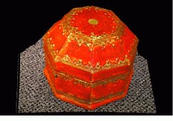
Following triangulation, surface smoothing is required to dampen the random noise of the digitizer. Then, spikes on the surface data resulting from stray laser-line reflections are removed. Next, texture data are placed on top of the derived geometry model using the texture coordinates obtained from the color-camera calibration parameters (see Fig. 2d).
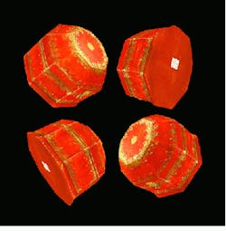
Last, the polygon count of the model is reduced to remove redundant points of the measurements that exceed the required resolution of the 3-D model (see Fig. 2e). These points are sorted in the order of their importance in a history file format, allowing the polygon count to be adjusted in real time.
Model construction
Constructing a good history representation is essential for fast image manipulation because 3-D imaging is compute-intensive, and the time needed to display large models tends to be lengthy. Available graphics-accelerator boards can draw about 500,000 triangles/s, 20,000 triangles/frame, or 10,000 vertices per frame. Moreover, because an average scan contains 25,000 vertices, it cannot be manipulated in real time. During scan gluing, or fusion, when a complete 3-D object is built from separate scans, 20 or more scans are often manipulated on the screen. Without reducing model complexity, however, scan gluing would be impossible to achieve.
Typically, the resolution of the original scan is reduced to about 5000 to 10,000 polygons, which is sufficient for object representation. The file size of such an object is about 30 kbytes when stored in MetaCreation`s MetaStream history-file format.
Image gluing is performed by a custom-software plug-in to the Ray Dream Studio software package from MetaCreations (Carpinteria, CA); it allows the building of 3-D models with textures from an arbitrary number of scans. During gluing, the initial rotation and translation functions between the two models are performed through a manual selection of at least three points on adjacent scans. After an initial approximation is found, the custom software finds the best rotation, translation, and zoom by automatically identifying all the matching points. Then, a cutting line is determined in the overlap model area. Next, the objects and textures are cut accordingly and blended to create a smooth, seamless image. Based on this image, a new geometric triangulation is built.
The final result is a 3-D model that can be stored in several available 3-D file formats. Some key applications include 3-D effects and digital content creations for the World Wide Web and movie and video productions, virtual-reality products, and medical imaging.
The use of off-the-shelf components coupled with several custom image-acquisition and data-processing algorithms have contributed to the design of a novel digital scanner that is capable of producing visually and geometrically accurate 3-D models in subsecond times. The custom-software plug-in for the Ray Dream Studio software package provides solutions for data acquisition, editing, polygon reduction, gluing of arbitrary numbers of models, and data saving in a progressive downloading file format.
MICHAEL PETROV is senior engineer at MetaCreations Real Time Geometry Laboratory, Princeton Junction, NJ 08550.
FIGURE 1. To digitize a 3-D model, the Real Scan 3D scanner generates laser stripes across an object using a galanometeric motor. A monochrome camera detects the laser-stripe positions. A color camera, installed between the laser source and the monochrome CCD camera, captures a texture map of the object. Scanner electronics is implemented on a single PCI card.
FIGURE 2. After capturing the images of one or several laser stripes using a monochrome CCD camera, the video signal is processed in real time by the fast laser finder, where laser-stripe positions are found with subpixel accuracy. Depth coordinates are assigned using calibration parameters stored in the scanner head (a). The digitized scanning results consist of an array of 3-D data points stored in fast-laser-finder memory (b). The imaging data are represented in triangulated form for use in 3-D graphics packages, and connectivity information is established between the original 3-D data points (c). In the subsequent data-processing step, the texture parameters are placed on top of the geometric data using texture coordinates derived from color camera calibration (d). The geometric data are filtered to dampen the random noise in the scanner, remove stray light reflections, and remove the low-fidelity digitized polygons. The reduced polygon count removes redundant data points (e).


