Vision-guided robots manage waste
Operating in a nonfixtured environment, a gantry robot, vision system, and 3-D guidance software seal radioactive-waste containers.
By Babak Habibi
The Idaho National Laboratory (INL) is a US Department of Energy national laboratory with extensive programs in nuclear science and radioactive-waste management. At the INL, engineers from contractor Battelle Energy Alliance are developing and constructing a prototype nuclear-waste-package closure system (WPCS) within a dedicated workcell. Several operations are performed within this cell to prepare the container for storage at a long-term waste-disposal facility, including closing the radioactive waste package, welding lids onto the waste-package container, filling the inner container with an inert gas, performing nondestructive inspection on welds, and conducting weld-stress mitigation. Because of the hazards of handling radioactive waste, these activities must be performed by automated, operator-interactive control.
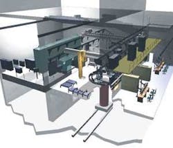
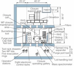
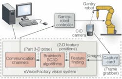
An important function of the WPCS control system is to position a remote handling system (RHS) to pick up and transport tools, equipment, and other objects within the closure cell. The RHS, a four-axis (x, y, x, r) gantry robotic system, grasps and transports end-of-arm tools from racks mounted in the cell to various positions on the waste package to perform closure-related functions. Periodically, the same tools and objects must be moved from the tool rack or the waste package to an adjacent glovebox for repair or maintenance (see Fig. 1).
null
The radioactive environment requires that grasping and transporting objects be accomplished with a high degree of precision to minimize the risk of pick-and-place failures. This operation should also take place in a nonfixtured and unstructured environment because the use of fixturing devices severely limits the flexibility of the cell and increases the potential for failure due to misaligned or malfunctioning fixtures. In addition, having to add a dedicated fixture for every object to be handled greatly increases the equipment count in the cell. The difficulties involved with removal, repair, replacement, and disposal of objects from a contaminated environment makes minimizing the number and complexity of equipment in the cell an important design goal.
To meet this design challenge, Battelle engineers have deployed a 3-D vision system to provide the gantry robot in the cell with the ability to locate tools and objects of interest. The 3-D vision-guidance system enables two critical robotic operations within closure cell. To accurately position tools and equipment relative to the waste package, the exact coordinates of the lid area are required since the location of the package can vary by ±2 in. in x, y, and z directions. In addition, a variety of tools and equipment must be moved from the closure cell to the maintenance glovebox for routine refurbishment and replenishment.
SYSTEM DESIGN
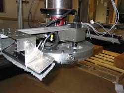
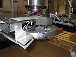
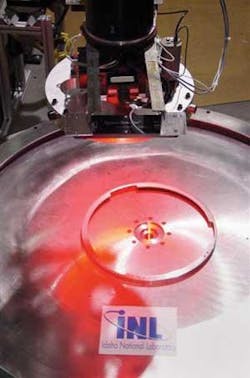
The WPCS 3-D vision-guidance system comprises a charge-injection-device (CID) camera manufactured by Thermo Electron CIDTEC that can withstand to at least 1 × 10⁶ rads total dose gamma radiation. The camera is equipped with a Tamron high-resolution lens and filtering to reduce glare and ambient light interference. Lighting is provided by two Spectrum Illumination Monster LED units that use high-brightness LEDs. These units are on either side of the camera mounted on the gantry z-mast (see photo, above).
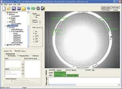
The vision-system PC runs Microsoft Windows XP and is equipped with a Matrox Meteor-II standard frame grabber, which receives an analog video signal from the CID camera mounted on the RHS gantry’s end effector. Running on the PC is the Braintech eVision Factory (eVF) software platform, including the Single Camera 3-D (SC3D) technology. SC3D uses a single image from one camera to determine the full 3-D, six-degrees-of-freedom position and orientation of rigid objects that provide a minimum number of visible object features (see Fig. 2).
Several alternative technologies were evaluated to provide the 3-D imaging, ranging from stereo imaging to laser and structured lighting. Rodney Shurtliff, advisory engineer, robotics and human systems, at Battelle, says, “We chose the SC3D technology because of its ability to provide precise 3-D location from a single image, its simplicity, and its track record in the automotive field. It does not require use of complex sensors, multiple cameras, and laser projectors; it also offers automatic calibration and part training, which means the systems can be maintained without dedicated vision specialists.”
The eVF platform uses the concept of a workspace depicted graphically as a hierarchical tree structure. Folders and subfolders within the tree contain the building blocks or components needed for the workspace to carry out operations. The workspace is logically divided into three sections: Global Resources, Global Runsteps, and Jobs. Designers can add and configure components into the tree structure as needed.
The Global Resources folder contains the basic “ingredients” needed to build and verify a typical vision-guided robotics (VGR) solution, including cameras, communication channels, calibrations to relate various coordinate systems, and tests to allow verification of the solution. The Global Runsteps section contains components that handle the initialization, runtime, and exit behavior of a workspace. The most typical component in the runtime subfolder is the CallJob component, which polls a communication channel-for example, that of a robot controller-and calls the proper eVF Job.
Once the Global Resources and Global Runsteps of a given workspace are populated and configured properly, one or more Jobs are added to the workspace to carry out the main operations. Each job is assembled by adding the required components in the proper order of execution. These components are then linked to one another as well as the proper global resources.
Consider the two jobs that calculate the 3-D position and orientation of each of the WPCS reference objects: the lifting ring and the tool plate. Each job begins with capturing an image of the object-the lifting ring attached to the waste package lid or the tool changer plate (see Fig. 3). The Viewport component is responsible for image capture and uses preconfigured parameters such as exposure time to provide image(s) to other components. The image is then passed onto the next component in the tree called the SC3D template.
Data are transferred between components by eVF’s data-pool mechanism and the user configurable connections that are made between the input of one component and the output of components further up in the tree. In this case, the image output of the Viewport component is connected to the image input of the SC3D template component. The SC3D template component that contains the SC3D algorithms has as ‘children’ a series of feature-finding components that locate the object features (landmarks) needed for the SC3D calculations. One of these features is used as an ‘anchor’ to limit the required search area for all other features.
A WriteData component sends the 3-D pose information to the designated communication channel-in this case Comm-Channel$RHS, which represents the communication channel to the RHS gantry controller. The WriteData component also sends the proper coordination flags to the communication channel to signal the gantry robot controller when the data are ready to be used.
Operation order
To perform a packaging operation, a waste package is first moved into the closure cell and positioned in the process opening, surrounded by a circular track. Two carriages-each consisting of a welding and inspection tool tray and a welding robot-are located on the track. The RHS is deployed to position the camera at nominal coordinates over the waste package.
At this point the RHS controller sends a signal to eVF indicating that the camera is positioned properly and requesting a specific job-in this case the job that locates the lifting ring-to be executed (see Fig. 4). eVF executes the job, which captures a single image of the scene and uses the SC3D algorithms to determine the position of the waste package in robot space. From this point, the 3-D information is used to position tools and end effectors relative to the waste package as well as to provide the welding robots with initial starting position coordinates.
Subsequently a specialized end effector is picked up and deployed to read the imprinted code on the inner lid to verify that the waste package in the closure cell matches the lids and other components that have been staged in the cell for the closure operation. The weld robots are then deployed to weld the first or inner lid in position on the waste package.
Welding and inspection are carried out by the welding robot system before evacuating and backfilling the waste package with helium. Once the inner lid has been welded in place, a purge port tool is deployed by the RHS to open a port in the inner lid. Using the vision-guidance system, the tool is placed and locked onto the inner lid. The waste package is evacuated and purged with helium before filling the package with helium and closing the port. A leak-detection ring is deployed to test for leaks in the inner lid weld. If all welds are sound, the equipment is removed from the waste package and returned to storage locations.
The middle and outer lids are, in turn, picked up in the closure cell by the RHS, placed on the waste package, and welded into place. A stress-mitigation process is performed on each weld, requiring specialized equipment to be picked up and placed-in each case the eVF 3-D vision-guidance system determines the location of tools and guides the RHS.
Following eddy-current and ultrasonic testing of the welds, the waste package is removed from the closure cell. The RHS picks up the tool trays from each weld system in turn and transfers them to a motorized cart, which transfers these one at a time into the maintenance glovebox. In the glovebox, a secondary RHS picks the tool trays from the cart and places them onto fixtured maintenance stations for refurbishment, repair, and testing. Following refurbishment or repair, the welding and inspection-tool trays are transferred from their maintenance station to the transfer cart and moved back into the closure cell. The RHS picks the tool trays from the cart using 3-D vision-guidance imaging and transfers the tool trays back to the weld system track or to a temporary storage location.
BABAK HABIBI is president and COO of Braintech; N. Vancouver, BC, Canada; www.braintech.com.
Company Info
Battelle Energy Alliance
Idaho Falls, ID, USA
www.battelle.org
Braintech
N. Vancouver, BC, Canada
www.braintech.com
Idaho National Laboratory
Idaho Falls, ID, USA
www.inl.gov
Matrox Imaging
Dorval, QC, Canada
www.matrox.com/imaging
Spectrum Illumination
Montague, MI, USA
www.spectrumillumination.com
Tamron
Commack, NY, USA
www.tamron.com
Thermo Electron CIDTEC
Liverpool, NY, USA
www.thermo.com
