Multiple cameras help perform intricate handling
Multiple cameras help perform intricate handling
By Dave Wilson
Then interpreted as an intricate robotics system, the human body is a versatile, mobile, detection system with all-encompassing vision, processing power, memory, sensory feedback, and movement. Comparatively, many industrial robotic inspection systems are still fairly primitive. Although robots used in mechanical and electronic assembly lines implement several axes of movement, they often have to be instructed by human operators to perform specific motion patterns.
To improve robot effectiveness, machine-vision designers are adding more sensory functions and devices. These include noncontact sensors, such as vision systems, and contact sensors, such as transducer force sensors. Whereas vision systems are used for visual input, contact sensors measure the components of force and torque from robot arms and grippers.
Mimicking the eye
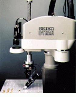
Many industrial robots use a single charge-coupled-device (CCD) camera to detect the parts being inspected (see Fig. 1). Generally, if more viewing information is required, more than one camera is used. In some applications, three cameras are attached to gather information in the x, y, and¥planes.
For example, a three-camera robotic system is being used in the inspection of fragile, fine-pitch surface-mounted devices (SMDs), according to Kevin Keras, marketing manager at Seiko Instruments Robotics Division (Torrance, CA). During robotic inspection, the SMDs are examined in a matrix tray feeder prior to selection and placement. A downward-facing camera attached to a robotic arm is directed over each part and determines whether the part is present. A second, fixed, upward-looking camera inspects the leads of the SMD for conformance to specifications. A third camera looks down onto the printed-circuit board for fiducial reference marks and then instructs the robot where to place the SMDs.
To build more reliable inspection systems, additional sensors such as vacuum sensors could determine whether the part was indeed picked up and placed. Whereas a vision system could be used for this function, a moving camera looking for parts would reduce overall system speed. For this reason, many robots have multitasking controllers that allow other sensors to check for parts presence while the robot arm is moving toward the placement area.
Integrated systems
A number of vendors are now offering completely integrated robot/vision systems. For instance, Seiko Instruments has produced a Microsoft Windows-based product called Vision Guide that uses an object-oriented approach as well as commercially available image-processing boards from Cognex Corp. (Natick, MA) and Matrox Electronic Systems (Dorval, Quebec, Canada). Calibration of the robot is automated, and operators need to learn only three commands to use the system.
For parts under inspection that are difficult to detect, such as parts stored in a bin with only one opening, stereoscopic viewing might solve the problem. In such a system, predominantly where range is to be measured, a pair of cameras or sonar transmitters and receivers can be used to acquire an image. A typical configuration, such as the one developed at the University of Rochester Vision and Robotics Laboratory (Rochester, NY), includes two movable color CCD cameras providing input to a MaxVideo image processor from Datacube Inc. (Danvers, MA). Camera motors are used to control both the tilt angle of the dual-eye platform and each camera`s pan angle. According to university research ers, camera movements of 400°/s can be achieved, which are somewhat close to human-eye movements of 700/s.
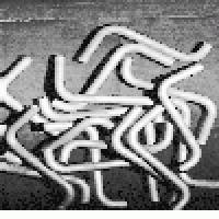
Three-dimensional (3-D) vision systems are preferred to manage more detailed tasks. At the Purdue University Robot Vision Laboratory (West Lafayette, IN), a 3-D vision system is recognizing tubular objects that are mixed together (see Fig. 2). The system, called the Tubular Objects Bin-Picking System, was originally developed with funding from Nippondenso (Japan); it is currently undergoing refinement for installation in a high-volume auto mobile-parts production line in Japan. In this system, an overhead light scanner illuminates the objects.
Following parts scanning, triangulation methods are usually implemented to generate a depth map of the scene. A sequence of processing steps, which include thresholding, edge detection, and noise removal, are then performed on the depth map to recognize specific patterns in the image. On a given scan of a random pile of tubes, the 3-D vision system generally recognizes between one and four complete tubes, in addition to between five and ten partial tube fragments.
However, experiments performed with the robotic system have indicated that structured light scanning is not a promising technique for image acquisition. Illuminating the many tiny holes and crevices of the parts results in extremely noisy images; therefore, robust depth-map generation is not possible. Consequently, system developers plan to use stereo vision to acquire the raw data.
Reducing scanning errors is important in binocular vision systems. For example, at the Robotics Institute of Carnegie Mellon University (Pittsburgh, PA), vision-system developers are using three cameras on their ranging platform, rather than two. The three cameras help to compensate for computational inaccuracy, introduce redundancy, reduce the chance of false matches, and increase overall system accuracy. Claimed to be one of the fastest depth-ranging systems ever implemented, the three-camera system is based on a 20 million-floating-point-operation-per-second synchronous computer.
Internal sensors
Whereas vision systems can guide a robot arm, tactile sensors perform delicate gripping and assembly operations. These sensors provide positional detail more accurately than vision systems can do alone. However, research performed on touch sensors and robots has been limited, despite the fact that multifingered robotic hands with touch sensors can move, probe, and change the vision-system environment.
As a robot approaches an object, the view from a conventional vision system might be obscured. Consequently, the combination of errors in the positioning of the gripper device with respect to the object proves difficult in applying the correct forces and torques. Having an imaging and/or a ranging sensor in the gripper can overcome this problem. Close-up imaging and ranging also provides information about an object`s surface shape and texture, a useful feature in an application such as following a weld line.
Jeremy Wilson, engineering manager of Kinetic Sciences (Vancouver, BC, Canada), says that in the Vision Skin Project his company explored for the Canadian Space Agency (CSA), a close-up imaging and ranging system was built into the fingertips of a robot gripper. Teaming with a silicon-micromachining group at Simon Fraser University (Burnaby, Canada), Kinetic Sciences researchers developed a close-up imaging and laser ranging sensor. The project was funded under the CSA STEAR (Strategic TEchnologies in Automation and Robotics) program, a long-term research initiative that supports Canada`s role in the International Space Station program.
If the objects in a particular scene are positioned in an unspecified location or orientation, an active robotic reasoning system can be used to seek and gather selective information by exploring the entire visual field based upon information that is relevant to the performance of a particular task. In the department of mechanical engineering and robotics research at the University of Surrey (Guildford, Surrey, England), John Pretlove and his team have built a mechatronic, lightweight, eye-in-hand sensor for this purpose. The function of the sensor is to provide enough information so that the robot can be guided to a known object at an unspecified location and orientation within a robot workcell. Once there, the robot can perform functions such as assembly, pick and place, bin-picking, visual tracking, and object interception in a conveyor system.
The ultimate machine
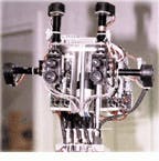
The Cog robot, which has been developed at the Massachusetts Institute of Technology (Cambridge, MA), nearly represents the ultimate robot. It contains a set of sensors and actuators that approximate human sensory and motor dynamics (see Fig. 3). The robot is directed by a scalable, multiple-instruction, multiple-data computer with 239 processor nodes. Each node has a Motorola 68332 microprocessor that communicates with front-end processor, motor controller, frame grabber, and display boards.
For Cog viewing, two monochrome CCD cameras are used to achieve disparity and approximate depth--important factors for object discrimination. This setup is able to closely duplicate human-eye speed and range of motion. Mounted on the robot`s head-like structure, the camera system moves with reasonable speed. It has a wide field of view for detection of objects and motion, a high-resolution capability, and a wide peripheral view.
Although machine-vision systems constitute a reliable means of acquiring imaging information about a scene, in applications such as robotics, sensors that provide tactile feedback are equally as important. New sensory devices are expected to empower robotic systems with increasingly more-effective detection and mobility capabilities.
DAVE WILSON is a science writer in London, England.
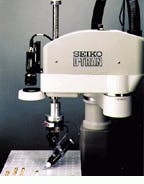
FIGURE 1. For pick-and-place parts-inspection applications, the D-TRAN system robot from Seiko Instruments can be fitted with a downward-facing camera to determine the presence of parts.
FIGURE 2. At Purdue University, a three-dimensional vision system called the Tubular Objects Bin-Picking System recognizes and localizes tubular objects. The intensity image shows a typical scene on which the system operates (top), while the resulting range map has been segmented into a set of tube fragments (bottom).
FIGURE 3. Under development at the Massachusetts Institute of Technology, the Cog robot can perform many human functions--except walking. Each robot eye consists of two monochrome charge- coupled-device cameras that approximate the wide peripheral view and high resolution of human eyes.
Company Information
Carnegie Mellon University
Pittsburgh, PA 15213-3890
(412) 268-2446
Fax: (412) 268-6944
Web: www.cmu.edu
Cognex Corp.
Natick, MA 01760
(508) 650-3000
Matrox
Dorval, QC, Canada H9P 2T4
(514) 969-6061
Fax: (514) 969-6273
Massachusetts Institute of Technology
Cambridge, MA 02139-4307
(617) 253-1000
Web: www.mit.edu
University of Rochester
Vision and Robotics Laboratory
Rochester, NY 14627
(716) 275-2121
Fax: (716) 275-2190
Web: www.rochester.edu
Datacube Inc.
Danvers, MA 01923-4505
(508) 777-4200
Fax: (508) 750-0938
E-mail: [email protected]
Web: www.datacube.com
Kinetic Sciences
Vancouver, BC, Canada V6T 1W5
(604) 822-2144
Fax: (604) 822-6188
E-mail: [email protected]
Web: www.kinetic.bc.ca/
Purdue University
School of Electrical and Computer Engineering
West Lafayette, IN 47907
(765) 494-0620
Fax: (765) 494-6440
Seiko Instruments
Factory Automation Division
Torrance, CA 90505
(310) 517-7850
Fax: (310) 517-8158
E-mail: [email protected]
Simon Fraser University
Burnaby, Canada
(604) 291-3111
University of Surrey
Guildford, Surrey GU2 5XH England
1483 259681
Fax: 1483 306039
E-mail: [email protected]
