Case study: Robotics and vision inspect molded parts
Incorporated in 1989 by founders Jim Dilbeck and Mike Roberts, Microplastics (St. Charles, IL, USA; www.microplasticsinc.com) uses injection-molding machines to produce thousands of insert-molded components in its 50,000-sq ft facility. Insert molding is an efficient alternative to the assembly of discrete parts using soldering, connectors, fasteners, or adhesives, with benefits that include reduced assembly time, labor costs, size, and weight, and increased reliability and design flexibility.
In insert-molding systems, a custom-built mold is loaded with inserts either robotically or manually. Molten plastic is injected into the mold. After cooling, the mold is opened and the components are removed and inspected. In serving the automotive, appliance, industrial-controls, and telecommunications markets, Microplastics works with engineering-grade resins and develops all its product and tool designs in-house. The company builds its own molds and uses its own automation designers and manufacturers.
The molding process
According to Doug Vandenburg, automation engineering manager at Microplastics, the company needed a system to control a process for two similar parts. The process begins with a reel of metal stampings that feeds a stamping die that separates the stampings from the reel. Individual stampings are then inserted into two boats that carry four stampings along a linear table. An M16i robot from Fanuc Robotics America (Rochester Hills, MI, USA; www. fanucrobotics.com) moves the boats from the blanking station and places them in a mold.
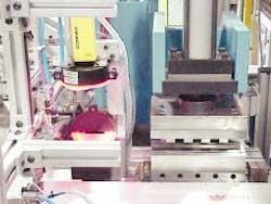
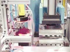
After the press completes the injection-molding process, the mold indexes so that the completed parts can be unloaded. The robot then unloads the boats from the mold and passes them to another linear table, leaving an empty mold positioned for the next molding sequence. The linear table feeds the molded parts to another blanking die that separates the electrical leads of the parts. After exiting the blanking die, the parts move to a vision inspection workstation where Cognex (Natick, MA, USA; www.cognex.com) Ethernet-based In-Sight 1000 and 3000 vision systems view the parts from both the top and the side. After verifying that the parts are within specification, bad parts are moved to a scrap chute and good parts are moved to a box filling station. A gantry system moves the boats back to the start of the line.
To control the entire process, Vandenburg chose Entivity (Ann Arbor, MI, USA; www.entivity.com) Studio, a control and human-machine-interface (HMI) package running under Microsoft Windows. Entivity Studio provides the control for the material handling, including moving the parts, coordinating when the robot should move and where, and controlling when the vision systems process an image. In addition to controlling movement and sequencing of boats and parts, Studio flow charts cue the robot and the injection machine, which run their own programs. The Studio HMI allows operators to switch between the two types of parts that run on the same production line. A single push of an on-screen button puts the Cognex vision systems off-line, loads a new vision program, and puts the system back on-line.
In addition to its primary control function, the PC monitors material use in real time, passing data to a Microsoft Excel spreadsheet using the dynamic-data-exchange method. The PC also collects pass/fail information provided by the Cognex vision systems. If too many parts fail in sequence, the Studio program flags the operator. Microplastics chose Studio because of its cost, integration of flow-chart programming vision control, built-in HMI, and ability to directly control the Animatics (Santa Clara, CA, USA; www.animatics.com) SmartMotor servo-motion-control system.
"The Cognex In-Sight 1000 and 3000 are cost-competitive," says Vandenburg, "and the company's PatMax pattern-matching and finding tool tracks the parts and provides greater accuracy than other systems. The Ethernet interface is key, and spreadsheet programming is easy to understand. In addition, it allows us to send images over the LAN already installed in the plant."
According to Vandenburg, the company developed the system 50% faster than expected because of the ease of Studio's programming. "We also have seen a dramatic reduction in downtime, because we can disassemble a part of the system for troubleshooting. Although the system took nine months to develop, control programming amounted to a very small percentage of this development time," says Vandenburg.
"We really didn't want to use relay ladder logic (RLL), which is common in programming PLCs. Instead, Entivity Studio allowed us to use flow-chart programming, with which systems developers can update or troubleshoot problems without lengthy training. With RLL, this would have taken much longer and would have been more difficult to maintain—especially if the original developer was not available," he adds. — Andrew Wilson

