Quick Pick
Robotic bin-picking workcell uses FireWire cameras and model-based analysis to unload water-pump parts
Grundfos, a Danish manufacturer of water pumps, used manual labor for many years to unload bins of rotor cans. For the past 15 years, the company has pursued robotic automation to improve productivity. Within the first 10 years of this effort, Grundfos succeeded in automating many simple manual tasks, but complex robotic workcells, such as picking from unstructured bins, continued to prove too difficult until recently.
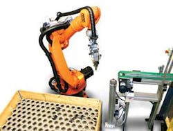
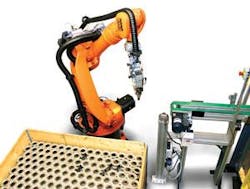
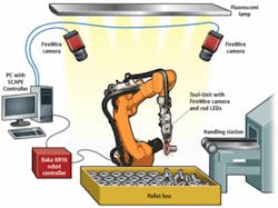
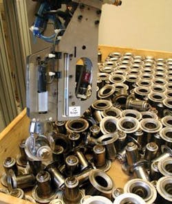
According to Grundfos senior engineer Michael Røddik, the company has now implemented its second robotic bin-picking workcell in partnership with Scape Technologies, achieving 98.3% uptime and cycle times 20% better than expected. The workcell picks rotor cans—which seal the rotor in the pump housing—from a bin containing eight individual layers. A pair of cameras mounted to a tower provides the system with a rough location of the parts, while a robot-mounted camera provides images to fine-tune robotic movements.
SCAPE Workcell Studio software running on a standard desktop PC called the SCAPE Controller calibrates the robot, vision, and bin-coordinate systems, while SCAPE Workcell Manager provides the GUI for the SCAPE Recognition Core algorithms for part location. Robot commands are sent from the Controller to various robot controllers via a separate software service called the SCAPE Communication Server, which also runs on the Controller.
Defining success
Each bin contains 2640 rotor cans in eight layers when it’s delivered to the conveyor-loading workcell. An Alfa low-energy circulator pump rolls off the back end of the Grundfos line every 10 seconds. Cycle times for locating, picking, and placing each rotor on the front end cannot exceed 9.5 s, or the risk of downtime will increase, thereby slowing the production line.
The rotors initially come closely stacked, but as the picking operation continues, the rotors become jumbled together, unstructured in location and orientation. Therefore, the system needs to be able to pick the rotor regardless of the part’s 3-D orientation. As each layer is picked, the robot must be able to remove the separating sheet so it can access the next layer. This process continues until the bin is empty.
“In the beginning of the Grundfos ‘robot epoch,’ the robot cells were rather simple,” explains Grundfos’ Røddik. “As robot vision became more accessible, more sophisticated robot applications were developed; but unstructured parts in boxes or bins [that were] not suitable for vibration feeders were left. Five years ago, we began to look for a reliable bin-picking system. The systems we found were too expensive, too slow, could not handle bins with four frames, and some were still dependent on mechanical feeders, with low reliability. We decided to enter a partnership with Scape Technologies—a spin-off from University of Southern Denmark—and its bin-picker solution looked promising to us.”
Homework first
The Grundfos bin-picker workcell uses a relatively simple hardware configuration for precision robotic guidance, along with a complex software approach designed to give the robot controller dynamic information about rotor location, orientation, and standard robotic gripping maneuvers that improve the chances of a successful pick. Prior to beginning operation, Scape Technologies engineers request a CAD file of the product—in this case a rotor can, according to Scape project manager Asim Ikram. “The CAD file is fed into a proprietary SCAPE Training program that allows the engineers to acquire virtual images of the CAD model with six degrees of freedom and choose features to be extracted,” adds Ikram.
This operation yields a database of features that will be used later by SCAPE’s Recognition Core software. This software is based on an open-source image-processing library IPL98 and Scape’s 3-D patented triangulation and location algorithms. “Within the next year, we expect to be finished with another program that will automatically find the best features for the Recognition Core software based on the submitted CAD file,” adds Ikram.
The Training program is also used to generate a number of effective gripping modes for the robotic end-effector, called the SCAPE Tool-Unit, based on the part and the grippers on the Tool-Unit. While 10 gripping modes may be a common number, Ikram says the Grundfos application required 15 gripping modes to ensure that the workcell would be able to pick all but a handful of rotor cans per bin (see Fig. 2).
In actuality, the system is picking almost 100% (0–4 parts may be left at the end) of the rotor cans using the database of gripping modes, each of which will be further qualified using volume information collected from the bin during calibration. Scape engineers combine the gripping mode with the 3-D position of a particular rotor can in the bin to sort the various approaches that a robot could make to grip the rotor can. By creating these databases in advance, says Ikram, the system can pick more reliably and faster because some of the robot path creation is done in advance, based on common locations, part poses, and gripping features.
With the recognition feature database and gripping modes in hand, the action moves to the workcell where calibration gets underway after robot cell construction. The Workcell Studio software controls the calibration process. Workcell Studio instructs the robot controller to move the Tool-Unit to 30 different positions within the bin volume and acquire an image with the first of two tower-mounted, high-resolution 2-Mpixel Marlin F-201B FireWire cameras from Allied Vision Technologies.
The two tower-mounted cameras are situated 1.8 m above the ground and 1.2 m apart and are separated by a panel of high-frequency, high-output fluorescent lights. At each of the 30 calibration positions, one of the two cameras acquires an image of a reference mark, a SCAPE calibration mark, mounted on the Tool-Unit. The calibration algorithm uses edge detection, blob analysis, and similar tools to locate the calibration mark in each image to calibrate the robot coordinate system with the cameras.
The calibration includes a nonlinear correction of radial distortion in the images. The same routine is performed for the second tower camera. The bin volume is measured by placing a frame on the top of the bin with SCAPE calibration marks in each corner. Images are then acquired from the two stationary cameras and full 3-D position information of the calibration marks is found by means of detecting the marks in each image and 3-D triangulation. These two cameras will eventually provide 3-D location data for rotors in the bin.
A final calibration routine is performed on the third camera inside the Tool-Unit, which provides images for fine robot guidance to each rotor can, using a SCAPE calibration mark mounted on the stationary camera tower of the workcell (see Fig. 3).
Serving up info
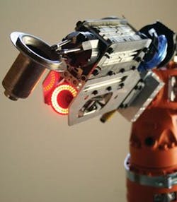
Scape has developed a modular Tool-Unit that contains an Allied Vision Technologies 0.3-Mpixel FireWire Guppy camera with a wide-angle, 4.5-mm GOYO Optical lens with red filter and CCS red LED ringlight (see Fig. 4). Multiple grippers can be mounted on the Tool-Unit, including the three-finger gripper used in the Grundfos application, as well as vacuum cups and other manipulators.
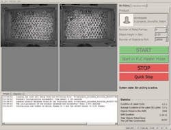
The operator controls the workcell through the Workcell Manager, a program running on the Controller. The Workcell Manager sits above the Recognition Core software and provides a GUI, as well as monitoring functions for the overall workcell operations. The operator has access to the bin-picking diagnostics and operations statistics through the GUI. The Controller communicates with the robot controller via an Ethernet or RS-232 connection. Communication between the Controller and robot controller, or controllers, is managed by a separate piece of software—Communication Server.
The Communication Server resides between the external robot controller and the Workcell Manager software running on the Controller. “The Communication Server supports any number of simultaneous connections, which makes it possible for SCAPE to control several robots simultaneously,” explains Rune Larsen, CEO of Scape Technologies.
After calibration, which only needs to be redone if cameras are disturbed or as part of a regular preventive maintenance program, the operator keys Workcell Manager to begin picking rotors and laying them on a nearby conveyor. With the robot arm positioned to one side of the bin, the two tower cameras acquire one set of images of the bin and transmit the images via FireWire to the Controller. The Recognition Core software uses 3-D patented triangulation and location algorithms and other image-processing algorithms such as edge detection and blob algorithms.
The feature information stored on the Controller PC in the feature database is also used in this process to locate individual rotors in each image. The result of the process is the exact 3-D position and orientation of each rotor: that is, six degrees of freedom, for up to 10 rotors from one image set. Those rotors are then prioritized for picking based on which rotors are oriented for easy picking, which again is based on information available in the previously defined grip modes stored on the Controller.
The Workcell Manager controls the prioritized lists of recognized rotors and sends a robot path for the most likely correct recognized rotor candidate to the Communication Server, which passes it to the Kuka KR16 robot controller. The robot moves the Tool-Unit to a location near the rotor to be picked and acquires an image with the tool camera inside the Tool-Unit for verification. Additional image processing confirms the rotor’s location and orientation. The data from this close-up image are used to confirm the selected rotor can pose or to reject the selected pose and trigger the robot to go to the next rotor in the prioritized list (see Fig. 5).
“Results from the tool camera verification are very precise because of the short distance and controlled light, thanks to the use of the red LED and red filter on the camera,” explains Ikram. “We’ve also used structured light and lasers instead of LEDs for this verification of parts during bin-picking.”
When the robot finishes unloading one layer, the Workcell Manager instructs the robot to start a separation sheet removal procedure using an add-on frame picked up by the robot. This add-on frame contains six suction cups in a grid almost as big as the bin plane. Emptying all 2640 rotor cans takes approximately six hours.
“The average cycle time is 7.6 seconds, and production uptime is 98.3%,” says Røddik. “Right now, a third project is under development that uses a robot to handle two small parts, from two boxes, and mount them in a fixture. In that operation, the robot uses only one camera mounted to the Tool-Unit, thus giving further flexibility and a very compact workcell.”
Scape Technologies has started to supply bin-picking to the market in collaboration with AH Automation, a Swedish automation integrator, says Rune Larsen.
null
