Fiberoptic lighting can fit machine vision
Cold, white light can be especially beneficial for inspecting products that require remote, nondestructive, high-illumination capability.
By Andrew Wilson, Editor
Lighting/illumination is probably the most important part of any successful machine-vision system design. Selecting illumination depends largely on the size of the part to be inspected, surface features, and geometry. In many machine-vision systems, fiberoptic lighting can be used in configurations that include ringlights, spotlights, backlights, and diffuse lights. With a number of vendors offering relatively similar systems, the choice of peripherals is a deciding factor in which cold, white-light fiber illumination system to choose.
In the design of their fiberoptic lighting systems, manufacturers use a variety of light sources that may or may not be optically coupled within an illuminator. Illuminators use stable power supplies to deliver either ac or dc power to the light source, which is then ported to a variety of external fiber fixtures that direct light output to the object under test. Because of the different types of applications that such devices are required to illuminate, a number of other features are often incorporated into the illuminator. These include potentiometers to adjust the intensity of light, ballasts for arc lamps such as metal halide, and color wheels or filters to provide a narrow spectrum of wavelength-specific light.
In choosing a white-light source for a particular machine-vision application, systems integrators should be aware of the numerous types of lamps that are currently available. For specialized applications such as UV and IR spectroscopy, dc deuterium lamps and pulsed deuterium lamps are often used. With wavelengths in the 160-400- and 180-400-nm range, respectively, the spectral distribution and stability of these lamps is ideal. In machine-vision systems, however, the need to produce cold, white light across the visible spectrum is of paramount importance. Here, a number of technologies including tungsten/halogen, xenon, metal halide, and fluorescent lamps are most often the lighting of choice.
Developers must understand the spectral output of each lamp, its operating mode and maximum power light output, and how it relates to the object being inspected. In specifying the color of individual light sources, a color temperature figure is often given. Measured in degrees Kelvin, the color temperature relates to the temperature at which a black body emits enough energy to produce a specific color. Thus, while candlelight may have a color temperature of 1500 K, incandescent, halogen, metal halide, tungsten, and xenon lamps will yield approximate color temperatures of 2700 K, 3000 K, 4200 K, and 5000 K, respectively.
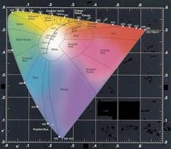
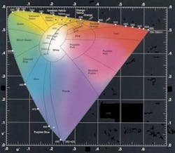
These color temperatures directly map to the CIE chromaticity diagram, which directly relates the color temperature to the visible spectrum (see Fig. 1). Lower color temperatures will appear warm white and reddish, higher color temperatures are cooler and will appear bluish in nature. “Because of this,” says Joe DiRuzza, director of sales at StockerYale, “using an opposite light spectrum will increase the contrast of any features that need to be inspected, while using a 5000 K xenon lamp to inspect, say, a blue cable assembly may not be a good choice since defect contrast will be reduced.”
The quartz halogen sources used in StockerYale fiberoptic illuminators are approximately 3250 K, 3400K, or 4200 K, depending on lamp type. “Because color temperature of a tungsten source is dependent on the voltage applied to the lamp, lower color temperatures are achieved at lower intensity settings. If a constant color temperature is required, a variable-aperture-iris or neutral-density filter must be used to vary light output,” says DiRuzza. This is in contrast to arc-based xenon and metal halide lamps, which, because they do not use a filament, are not susceptible to this effect.
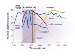
Spectral output of the illumination source is another important parameter that must be understood when specifying a fiberoptic source. By charting the spectral output and frequency of a number of different lamps such as tungsten, xenon, fluorescent, and metal halide, systems integrators can determine the characteristics of each individual lamp across the electromagnetic spectrum. The visible spectrum is between approximately 400 and 750 nm, with UV below and IR above (see Fig. 2).
To provide a true color image, light sources should exhibit an even output across the spectrum, and IR radiation should be minimized because it is converted to heat. Ideally, in machine-vision applications, lamps should be chosen to meet specific spectral requirements and exhibit low output at other wavelengths. As can be seen, arc lamps such as xenon and metal halide are primarily UV to visible light sources, while metal halide lamps produce a strong (if not uniform) response in the visible region. For long-wavelength visible to near-IR, quartz tungsten halogen lamps are a good choice.
The way in which a lamp’s output is quoted also can be confusing, but for machine-vision applications it may only be necessary to consider the luminance within the visible spectrum being concentrated onto the lightguide. This is generally expressed as candelas per square millimeter (cd/mm2). Specifying the luminous flux of a source in lumens, however, only defines the total output energy of the lamp. Because many fiberoptic-based machine-vision systems use external fiber fixtures that illuminate the part under test from a specified direction and distance, designers should specify intensity and uniformity of the light as an illuminance value that measures intensity of light from a given direction.
Since materials reflect, absorb, or refract differently, the luminance value can change with the surface type, while the illuminance value remains constant. Illuminance is typically expressed in lux (lumens per square meter) or foot-candles (lumens per square foot). Unfortunately for systems integrators, many lighting manufacturers do not specify either the luminance or illuminance values of their products in their data sheets. And, while some specify a luminance value for their light sources, others, such as StockerYale, have more properly specified their light sources in illuminance values.
For many high-speed machine-vision applications, it is necessary to use strobed illumination techniques to produce high-intensity, short pulsewidths of wide spectral light distribution. While filament sources such as tungsten lamps cannot be pulsed, arc sources such as xenon and metal halide lamps are ideal for the purpose. By applying a high-voltage pulse to the lamp to ionize the gas in these short-arc flashlamps, cycles of less than 1 µs can be achieved. Although xenon flashlamps provide continuous optical energy in the visible region, they can be used with filters to provide illumination for IR illumination.
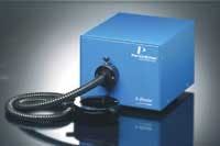
PerkinElmer’s X-Strobe series, for example, includes variable intensity control and produces pulses of radiant energy covering the ultraviolet (UV), visible, and near-IR (see Fig. 3). Several variations of the X-Strobe are available with different light output and flash rates. An ac power supply recognizes ac voltage from 100 to 240 V, with line frequencies from 50 to 60 Hz. Various nosepieces and adapters are available in sizes up to 1 in. in diameter to fit with the most common fiberoptic bundles.
Since metal halide lamps have a flash efficiency approximately four times higher than halogen and xenon lamps, they can produce an output four times higher with the same power consumption. GE Lighting’s latest lamps, for example, have 100-lm/W efficiency and are offered in versions of up to 12,000 W with a typical daylight color temperature of 6000 K. As their color-temperature characteristics are similar to daylight color, these lamps are useful in machine-vision systems where color matching is a requirement.
In machine-vision applications, selecting the type of lighting needed largely depends on the size, surface features, and geometry of the part to be inspected. Most often, the greatest need of the machine-vision systems developer is to enhance the contrast of the part being inspected. Because of this, fiberoptic illuminator vendors offer add-on components such as light guides, ringlights, goosenecks, line arrays, and backlights to meet these demands. Illuminators such as light guides, for example, that focus light into coherent, tight beams produce specular (or hard) illumination while fiberoptic ringlights produce an even, more diffuse, softer illumination.
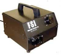
Several companies produce such add-in peripherals. For its quartz-halogen-based Model FI-1060 visible light illuminator, for example, Fiberoptic Systems offers peripherals that include line-light converters, ringlights, and goosenecks (see Fig. 4). Where diffuse or specular surfaces must be examined, ring illuminators are economical and practical choices, while dome illuminators can be used to illuminate shiny, bumpy surfaces.
To silhouette an image for measurement purposes, backlights provide sharp contrast to outline a parts shape, hide clear housings, and view openings such as drilled holes. Here, too, a number of company’s produce fiberoptic area backlights that are offered in a number of different sizes. Dolan-Jenner and StockerYale, for example, both offer backlights as large as 6 × 8 in.
For laser embossing, engraved marks, or surface defects, darkfield illuminators dramatically enhance the contrast of surface features by illuminating the part under test at highly oblique angles. In semiconductor inspection, for example, polished wafers are very reflective and on-axis or bright-field illumination normal to the wafer results in a reflection of the illuminator or bright spot; thus off-axis or dark-field illumination is the better choice. Diffuse on-axis illumination provides diffuse, uniform collimated illumination within the camera’s optical path. However, because unpolished wafer features cast shadows with low-angle darkfield illumination, bright-field illumination must be used.
According to StockerYale’s DiRuzza, the company’s standard fiberoptic on-axis illuminator uses a 50/50 beamsplitter to direct a diffuse light source coaxial with the optical axis of the application. In applications such as inspecting CD-ROMs, foil packs, and other shiny metallic objects, the use of on-axis coaxial lighting virtually eliminates the presence of shadows and glare.
With the large number of vendors now offering fiberoptic illuminators, machine-vision systems designers can choose from a plethora of products and peripherals. In describing their products, however, many of these vendors tend to omit critical performance specifications needed to correctly compare illuminators. For this reason, integrators may opt to use well-established vendors who, understanding the needs of OEMs, may be willing to allow their systems to be evaluated.