Telescopic system uses low-light-level imaging to enlighten space objects
Telescopic system uses low-light-level imaging to enlighten space objects
By John Haystead, Contributing Editor
A top the 10,023-ft summit of Mt. Haleakala, a dormant volcano approximately 90 miles east of Hickam Air Force Base (Maui, HI), sits the Maui Space Surveillance Site (MSSS)--the US Air Force`s largest optical space tracking facility. In 1999, the facility is scheduled to be upgraded with a 3.67-m advanced electro-optical system (AEOS) telescope that will incorporate both visible and infrared (IR) imagers, a photometer/radiometer, and an adaptive-optics system to provide nearly a threefold increase in resolution over other available visible imaging sensors. In operation, the telescope is anticipated to resolve 4-in. objects approximately 180 miles away in space.
Researchers at Kirtland Air Force Base (Albuquerque, NM) are developing the telescope system, whereas the 3.67-m optical system is being built by Contraves USA (Pittsburgh, PA). Following test and evaluation, the optical system will be delivered to the Air Force, which will use it to track orbiting satellites, space debris, and asteroids.
By incorporating a 3.67-m primary mirror, the telescope is calculated to provide a satellite-tracking capability of 17°/min with a field of view of 1 mrad. Independent of any additional sensors, the telescope system`s theoretical resolution in zero atmosphere is 10 cm for objects 400 km away in the visible region and 100 cm in the IR.
Built by the Boeing Rocketdyne Division (Canoga Park, CA), the AEOS observatory control system (OCS) directs the movement of the 100-ton telescope, continually compensates and corrects its alignment, and handles the communications among the telescope systems and computers. The control system also collects and distributes data from the optical system`s sensor systems and distributes the data to the facility`s processing laboratories and other off-site facilities. The AEOS observatory control system will also provide a notable upgrade to the overall MSSS because it will also be integrated with four other telescope systems installed at the site.
The OCS is a distributed system made up of embedded controllers for Sun Microsystems (Mountain View, CA) UNIX and Silicon Graphics (Mountain View, CA) workstations, all interconnected via Ethernet and ScramNet (shared common RAM network) lines. Robert Lytle, Boeing Rocketdyne research and development program manager, says, "Some of the software is being reused from existing systems, while all new software is being written under the UNIX operating system in C++."
Radiometer design
The optical system`s first sensor is an advanced radiometer. Built by Mission Research Corp. (Santa Barbara, CA), the radiometer covers the 0.3- to 22-µm spectral band. Although the original requirement for the system specified the detection of very dim 18th-visual-magnitude (Mv18) stars, the radiometer is capable of detecting Mv22 stars or better, according to Thomas Old, Mission Research vice president.
Incorporating four 128 ¥ 128 focal-plane arrays (FPAs), the radiometer`s visible channel array was built by Sarnoff Corp. (Princeton, NJ), its medium-wave array by Hughes Aircraft (El Segunda, CA), and its long-wave and very-long-wave arrays by Rockwell Research Center (Thousand Oaks, CA).
"Wavelengths of interest for the optical system`s primary satellite tracking and orbital-debris-analysis mission are not always compatible with astronomical observations. This has been compensated for with additional astronomical FPAs, particularly the medium-wave array," explains Old. Each FPA channel has two integrated filter wheels, one with six neutral-density filters and one with six bandpass filters.
The radiometer optics and electronics are located alongside the main telescope trunnion. Data from each array are first collected and pro cessed by a system processor from SE-IR (Goleta, CA), which is mounted directly beneath the instrument. The processing system is actually four systems running in parallel with two parts to each system.
The "camera-head" portion of the system consists of a 4 ¥ 6-in. Euro-card form factor rack holding four independent backplanes, one for each FPA, and incorporates the bias supplies, clock drivers, and analog-to-digital (A/D) converter boards. Although packaged in a Euro-card form factor, the data bus is a proprietary design. In total, 40 A/D boards are used, all with a single 12-bit 5-Msample/s converter. Both the long-wave and very-long-wave detectors feed 16-A/D-board backplanes, while the medium-wave and visible arrays contain four A/D boards each (see figure on p. 48).
System design
The A/D output from each sensor is multiplexed into a single 16-bit-wide video data stream and is carried by one of four RS-422 parallel interfaces from the camera-head system to the Pentium-PC-based DSP system located about 1.5 feet away. The maximum aggregate throughput of the four interfaces is approximately 160 Mbytes/s. The signal processor holds four sets of 16-bit DSP and timing-generator boards on an ISA bus backplane, which is used for control purposes.
"We designed our own pipelined DSP boards," says Mark Stegall, SE-IR president, "because we couldn`t find any existing processors capable of handling the speeds we needed." The signal-processor boards are used toperform real-time two-point linear correction of each pixel followed by pixel reordering, as well as to mirror and/or rotate images as a means to correct for different optical configurations.
Video data from the DSP boards is then passed down one of four Fibre Channel links to the combined VME-based real-time signal-processing system (RTSPS) built by Delphi Engineering Group (Costa Mesa, CA) and the OCS telescope control subsystem (TCS) built by Saturn Systems (Duluth, MN). Two FCX40 DSP/ Communication boards from DSP Fibre Channel Systems (Culver City, CA) handle the communications for each channel.
Each board also incorporates a TMSC40 DSP from Texas Instruments (Dallas, TX) to handle data conversion and formatting. Although the Fibre Channel bus can operate up to 100 Mbytes/s, the system is currently running at about 33 Mbytes/s. An additional fiberoptic Ethernet link carries system-status data such as array temperature and filter-selection information.
The RTSPS/TCS performs radiometric-intensity measurements, as well as providing real-time target-position and tracking-error reports to the telescope to keep it properly sighted on moving targets across the sky. These calculations are performed by a series of pipelined 50-MHz TMSC40 processors on five Quad-C40 boards from Mizar Inc. (Carrollton, TX). A single Quad-C40 handles the data from each of the three 200-frame/s infrared arrays, while two boards are dedicated to the visible sensor. Although the visible pipeline can handle up to 1000 frames/s, the array is currently generating data at 500 frames/s.
To detect and track otherwise-invisible targets from background noise, the mirror of the AEOS telescope can be programmed to wobble like a dropped plate, or "dither," at a 20-Hz rate. As the telescope dithers, light energy from the target moves about the sensor arrays. Because the target energy remains constant, however, by collecting and comparing the data from each frame in real time, the RTSPS can remove the background noise. Next, because the target will appear to be moving in circles over multiple image frames, the RTSPS also performs registration calculations to move the target back to the center of each frame. Other noise-reduction techniques such as pixel averaging and application of spatial-matched filters are also applied to the data, all in real time.
All the Quad-C40 and Fibre Channel boards are housed in one VME-bus chassis. A second VME rack holds the TCS system`s Motorola 68040 CPU board running VxWorks, a Datum Bancomm (San Jose, CA) IRIG-B time-code-reader board, and an Interphase (Dallas, TX) fast/wide 5-Mbyte/s SCSI interface to a Seagate (Scotts Valley, CA) Barracuda storage drive. The two racks are linked by a pair of Multisystem eXtension Interface (MXI) bus boards from National Instruments (Austin, TX).
As explained by Delphi principal engineer Dave Snope, "There were just too many boards and too much data being transferred to use a single VME chassis for the entire system." Because the data rates are markedly reduced by the time they get to the VME/MXI bus (4 Mbytes/s), the bus is able to handle the load.
The TCS receives data reports from the RTSPS and passes them on to the OCS`s Sparc-20-based executive control computer via a ScramNet data network board from Systran (Dayton, OH). Developed by the Air Force, the shared common RAM network is a replicated shared-memory, 150-Mbit/s fiberoptic communication system with a data latency per node of 250 to 800 ns with up to 256 nodes (separated by up to 3500 m) on a single fiberoptic ring.
Saturn Systems developed the control system software for the camera, the filter wheel controllers, and system integration to the OCS. The real-time software and the client/server architecture manage approximately 20 concurrent processes running on three separate operating systems--the Wind River Systems` (Alameda, CA) VxWorks 5.2 real-time operating system running on the TCS; the Sun Microsystems` Solaris 2.4 on the OCS, and Microsoft (Redmond, WA) Windows NT 4.0 running on the SE-IR system. They allow full local or remote control of the radiometer instrument. Approximately 95% of the software is written in C++, with the remainder in C and assembly for low-level device interfacing.
Adding spectrographs
In 1999, the Maui Space Surveillance Site will also be equipped with the University of Hawaii Institute for Astronomy`s optical/infrared spectrograph. The optical system will consist of two cross-dispersed echelle spectrographs, one for the 0.5 to 1.0-µm spectrum, and one for the short-wave infrared region from 1.0 to 2.0 µm. "Spectral measurement at near-infrared wavelengths is used to detect faint stars because dust absorption at shorter optical wavelengths makes most of these stars undetectable," says Don Mickey, Institute for Astronomy principal investigator.
"The principal design goal is to provide a system capable of recording high-resolution spectra of astronomical objects in a single exposure," says Klaus Hodapp, Institute for Astronomy scientist. For that reason, the spectrographs use large-format detectors. The visible CCD camera, built by MIT Lincoln Laboratory (Lexington, MA), incorporates a mosaic of four 2k ¥ 2k devices (8192 ¥ 8192 pixels). The infrared camera uses a 2048 ¥ 2048 pixel HgCdTe detector enclosed in a cryogenic container, all supplied by the Rockwell Science Center.
According to Mickey, the CCDs will permit extended red response with quantum efficiency above 80% at 900 nm and 30% at 1000 nm. The optical/infrared spectrograph will not use the adaptive optics system, but will take uncompensated light directly from the 3.67-m telescope. It will have its own adaptive optics system, which, while providing a lower degree of correction than the main system, will allow the spectrograph to image reference stars as faint as Mv15.
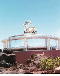
Mt. Haleakala in Maui, HI, will be the future site of the US Air Force Advanced Electro-Optical System telescope.
Adaptive optics improves image resolution
Fitting an adaptive-optics system to the Mt. Haleakala Advanced Electro-Optical System telescope is expected to dramatically improve its image resolution by dynamically correcting the wavefront propagation aberrations caused by atmospheric turbulence.
"The atmosphere typically creates an angular blur of about 1 to 3 arc sec, but the adaptive optics will reduce this to the limits of the telescope aperture, or a small fraction of an arc second. Correction of a 3-arc sec blur to 1/30 of an arc second provides a 100-fold improvement in resolution," says Bill Zmek, Hughes Aircraft optical systems engineer.
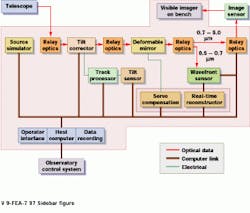
In operation, the beam from the exit pupil of the 3.67-m telescope is imaged by relay optics onto a tilt-corrector mirror (see figure). The beam is then re-imaged onto a deformable mirror. A set of more than 900 piezoelectric actuators on 9-mm centers behind the deformable mirror`s face sheet can alter its shape by up to ۬ µm.
Part of the light is then relayed to a Hartman wavefront sensor, which, in turn, provides wavefront slope information over a fiberoptic data link to a real-time reconstructor computer. This computer takes the slope information and processes it into phase-correction maps for the deformable mirror.
After correction by the deformable mirror, the optical image is relayed to a CCD camera with a 512 x 512 x 12-bit/pixel array. "The accumulated wavefront error introduced throughout the optical system is about 1/10 wave rms," says Hughes Aircraft program manager Ira Schmidt.
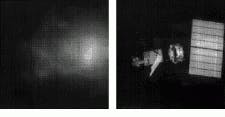
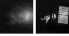
In conjunction with the Advanced Electro-Optical System telescope, a real-time reconstructor computer controls a deformable mirror in real time assisted by a wavefront sensor. Simulation of the system (inset) demonstrates that the processed images show much greater resolution than the uncorrected versions.
Four subsystems make up the signal-processing system for the 3.67-m Advanced Electro-Optical System telescope, which is part of the US Air Force Maui Space Surveillance Site. The image signals captured by the focal plane arrays (top left) are preprocessed using an EISA bus-based system. After five Quad-C40 boards perform radiometric intensity measurements and tracking reports, data are passed to the observatory control system over a shared common RAM network (ScramNet) interface.
